Sound insulation floor structure and sound insulation floor component as well as method for reducing floor impact sound

a sound insulation floor and sound insulation floor technology, applied in the direction of shock-proofing, walls, flooring, etc., can solve the problems of local deformation of wood boards, subsidence of members, uncomfortable foot-step feeling, etc., to improve floor impact sound insulation, prevent floor structure subsidence, and improve the effect of sound insulation

Active Publication Date: 2013-01-31
KURARAY CO LTD
View PDF8 Cites 16 Cited by
  • Summary
  • Abstract
  • Description
  • Claims
  • Application Information

AI Technical Summary

Benefits of technology

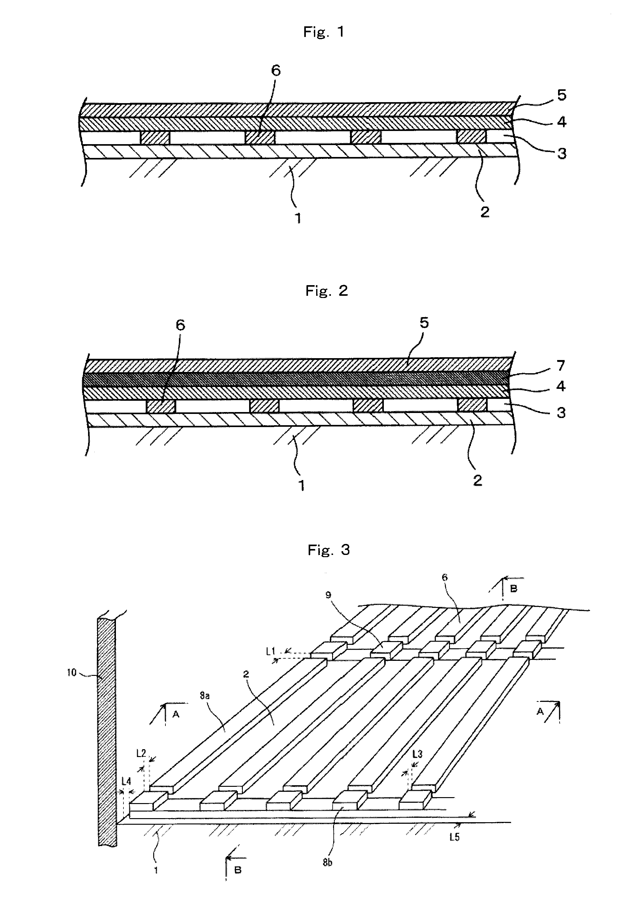
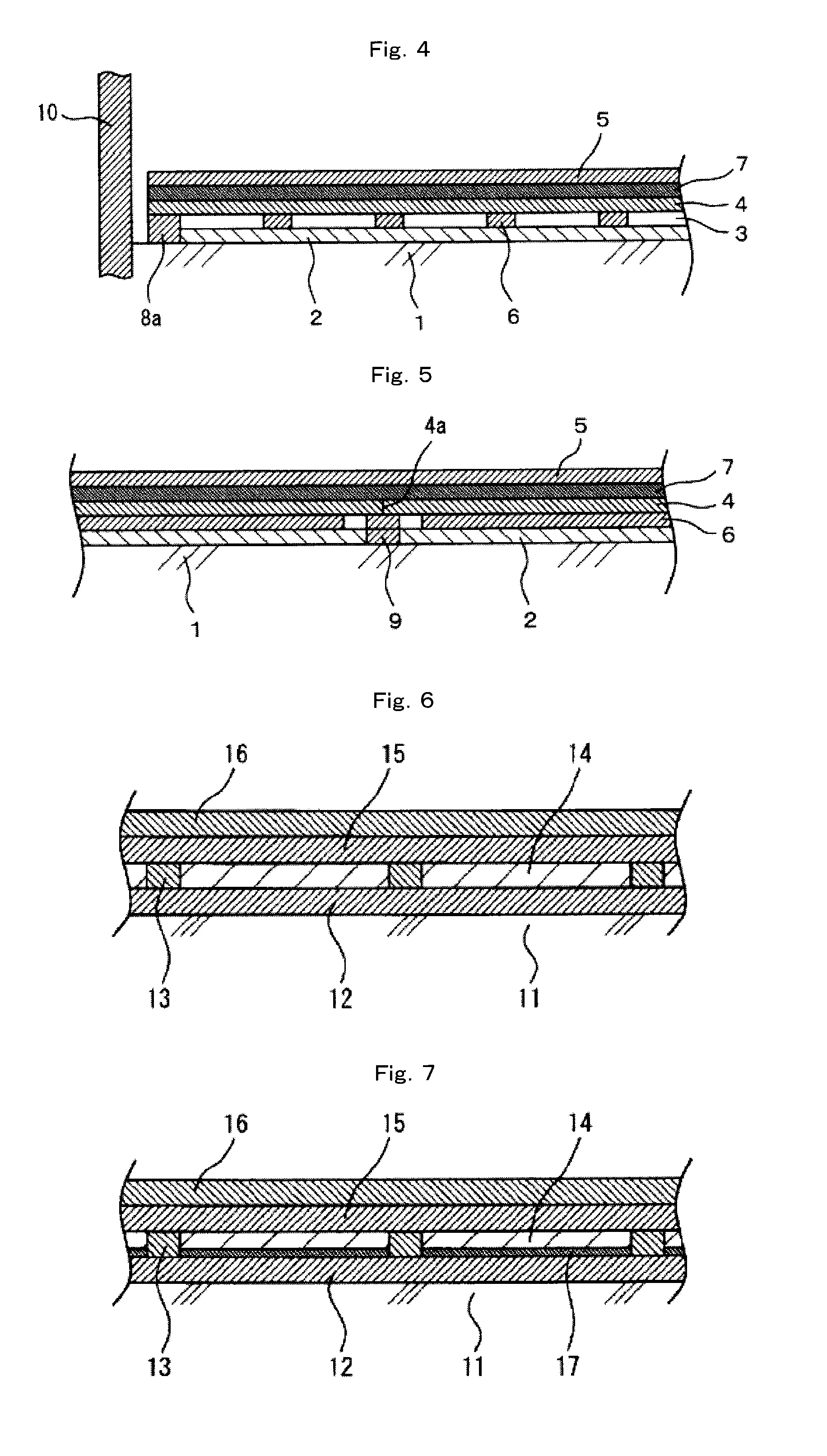
[0023]According to one aspect of the present invention, since a floor structure comprises an intermediate layer, which is interposed between a floor backing member and a floor finishing layer, comprising a buffer member formed with a specific nonwoven structure comprising a thermal adhesive fiber under moisture which is melt-bonded to a fiber for the nonwoven structure to fix the fibers, the floor structure is prevented from subsiding caused by walking. In addition, the floor structure achieves comfortableness to walk and has improved floor impact sound insulation.
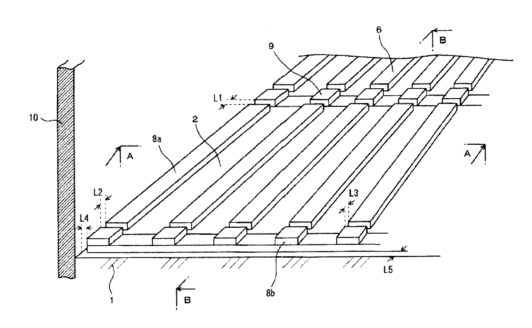
[0024]When the intermediate layer is formed with a plurality of joists disposed parallel to each other at intervals and a plurality of buffer layers while disposing the joists and buffer layers alternately, and the floor structure comprises, in sequence, the intermediate layer, an air layer, a hard layer having no kerf formed thereon, and the floor finishing layer and further comprises a support member in the air layer between the buffer layer and the hard layer; the hard layer is bonded to the floor finishing layer in tight contact, and there is a space portion between the buffer layer and the hard layer by the support member. The floor structure therefore has a large space portion compared with a conventional floor structure having a kerf and allows a floor impact sound from upstairs in a multi-storied building to be blocked in a wide frequency range including a low-frequency zone. Thus the floor structure can achieve effective insulation against both light-weight floor impact sound and heavy floor impact sound.
[0025]Moreover, a floor structure having a moderate and uniform hardness can be achieved by compressing a compressable layer having a thickness larger than the thickness of the joist to the thickness of the joist in the intermediate layer, and the floor structure also has an excellent safety in falling down.
[0026]When the sound insulation floor structure further comprises a damping layer, the floor structure can reduce a vibration derived from a floor impact source by the damping effect to improve floor impact sound insulation. In particular, a damping layer containing an asphalt not only can achieve improved floor impact sound insulation but also can improve comfortableness to walk.
[0027]Further, the buffer layer comprising the buffer member can ensure a withstand load while maintaining a buffering property providing insulation against a high-frequency floor impact sound (particularly, a light-weight floor impact sound). In addition, combination of the buffer layer and the joist can improve the strength of the floor member and highly prevent the subsidence or the like. Moreover, the joist formed with the buffer member can prevent a vibration spreading through the joist and improve insulation against a further high-frequency floor impact sound.

Problems solved by technology

For the method using combination of the kerf and the buffer member, however, the wood board is locally deformed in a region loaded by walking (that is, the floor member subsides) even when the specific medium-density fiber board is disposed on the surface side.
Thus there is an uncomfortable foot-step feeling during walking.
Further, the floor has a small sound insulation effect on a heavy floor impact sound (for example, a relatively low-frequency sound wave), probably because the floor has a small space volume due to the insufficient size of the kerf.

Method used


Image

  • Sound insulation floor structure and sound insulation floor component as well as method for reducing floor impact sound
  • Sound insulation floor structure and sound insulation floor component as well as method for reducing floor impact sound
  • Sound insulation floor structure and sound insulation floor component as well as method for reducing floor impact sound

Examples


production example 1

of Buffer Member

[0215]A sheath-core form conjugated staple fiber (“Sofista” manufactured by Kuraray Co., Ltd., having a fineness of 3 dtex, a fiber length of 51 mm, a mass ratio of the sheath relative to the core of 50 / 50, a number of crimps of 21 / 25 mm, and a degree of crimp of 13.5%) was prepared as a thermal adhesive fiber under moisture. The core component of the conjugated staple fiber comprised a polyethylene terephthalate and the sheath component of the conjugated staple fiber comprised an ethylene-vinyl alcohol copolymer (the content of ethylene was 44 mol % and the degree of saponification was 98.4 mol %).

[0216]Using the sheath-core form conjugated staple fiber, a card web having a basis weight of about 50 g / m2 was prepared by a carding process. Then six sheets of the card webs were put in layers to give a card web having a total basic weight of about 300 g / m2.

[0217]The resulting card web was transferred to a belt conveyor equipped with a 50-mesh stainless-steel endless net...

production example 2

of Buffer Member

[0221]A nonwoven structure having a thickness of 12 mm was produced in the same manner as in Production example 1 of buffer member except that a card web having the number of stacked webs of 17 and a total basis weight of about 850 g / m2 was used and that the clearance (distance) between the upper and lower conveyor belts was adjusted appropriately. The obtained nonwoven structure had an apparent density of 0.07 g / cm3. The nonwoven structure had bonded fiber ratios of 11% at the surface area, 10% at the central area, and 10% at the backside area. The nonwoven structure was cut to give a buffer member 1.

production example 3

of Buffer Member

[0222]A nonwoven structure having a thickness of 3 mm was produced in the same manner as in Production example 1 of buffer member except that a card web having the number of stacked webs of 12 and a total basis weight of about 600 g / m2 was used and that the clearance (distance) between the upper and lower conveyor belts was adjusted appropriately. The obtained nonwoven structure had an apparent density of 0.2 g / cm3. The nonwoven structure had bonded fiber ratios of 73% at the surface area, 70% at the central area, and 74% at the backside area. The nonwoven structure was cut to give a buffer member 3.


PUM


Abstract

A sound insulation floor structure comprises a floor backing member, a floor finishing layer, and an intermediate layer between the floor backing member and the floor finishing layer, the intermediate layer comprising a buffer member comprising a nonwoven structure. The nonwoven structure comprises a thermal adhesive fiber under moisture which is melt-bonded to a fiber of the nonwoven structure to fix the fibers. For example, the sound insulation floor structure may comprise, in sequence, a floor backing member 1, a buffer layer 2, an air layer 3, a hard layer 4, and a floor finishing layer 5. In the floor structure, a support member 6 is disposed between the buffer layer 2 and the hard layer 4. The support member may occupy 10 to 70% of a floor area. The sound insulation floor structure prevents subsidence of a floor member due to walking, achieves comfortableness to walk, and has improved floor impact sound insulation.

Description

TECHNICAL FIELD[0001]The present invention relates to sound insulation floor structures and components useful for reducing floor impact sounds (for example, a floor impact sound from upstairs in a multi-storied building) and to methods for reducing floor impact sounds.BACKGROUND ART[0002]Sound insulation floor structures are applied to multi-storied (or multi-story) buildings (e.g., an apartment house or a condominium, a building, and a dwelling house) in order to reduce floor impact sounds from upstairs. The floor impact sounds include a light-weight impact sound (a relatively high-frequency sound wave) [such as an impact sound caused by dropping of tableware such as a spoon or an impact sound caused by walking with house shoes (or slippers)], an impact sound (a relatively low-frequency sound wave) [such as an impact sound caused by jumping of a child down from a sofa or an impact sound caused by noisily walking], and the like. The sound insulation floor structures are desirable to...

Claims


Application Information

Patent Timeline
Patent Type & Authority Applications(United States)
IPC IPC(8): E04B1/84
CPCE04F15/225E04F15/203E04F15/20E04B1/84E04B1/98E04F15/02044E04F15/107E04F15/206E04B2001/8466E04F2290/044E04F2290/041E04F2015/02055
Inventor MIYAKE, NOBORUTAKAMATSU, MASAHIKOKANEZAKO, HIDEKIHIRATA, KAZUTOSHIHAYASHI, KOHEIKIYOOKA, SUMITOADACHI, ATSUMIKOIKE, MASARUKOIZUMI, SATOSHI
Owner KURARAY CO LTD
Why Eureka
Try Eureka