Near-rail noise reducing device at T-beam and mounting method of noise reducing device
An installation method and noise reduction technology, applied in the direction of noise absorbing devices, buildings, etc., can solve the problems of high limit of sound barrier height, limited load bearing, hidden safety hazards, etc., to eliminate hidden safety hazards, solve construction troubles, and reduce design height. Effect
- Summary
- Abstract
- Description
- Claims
- Application Information
AI Technical Summary
Problems solved by technology
Method used
Image

Examples
no. 1 example
[0046] Embodiment 1: The sound barrier is installed above the ballast retaining wall.
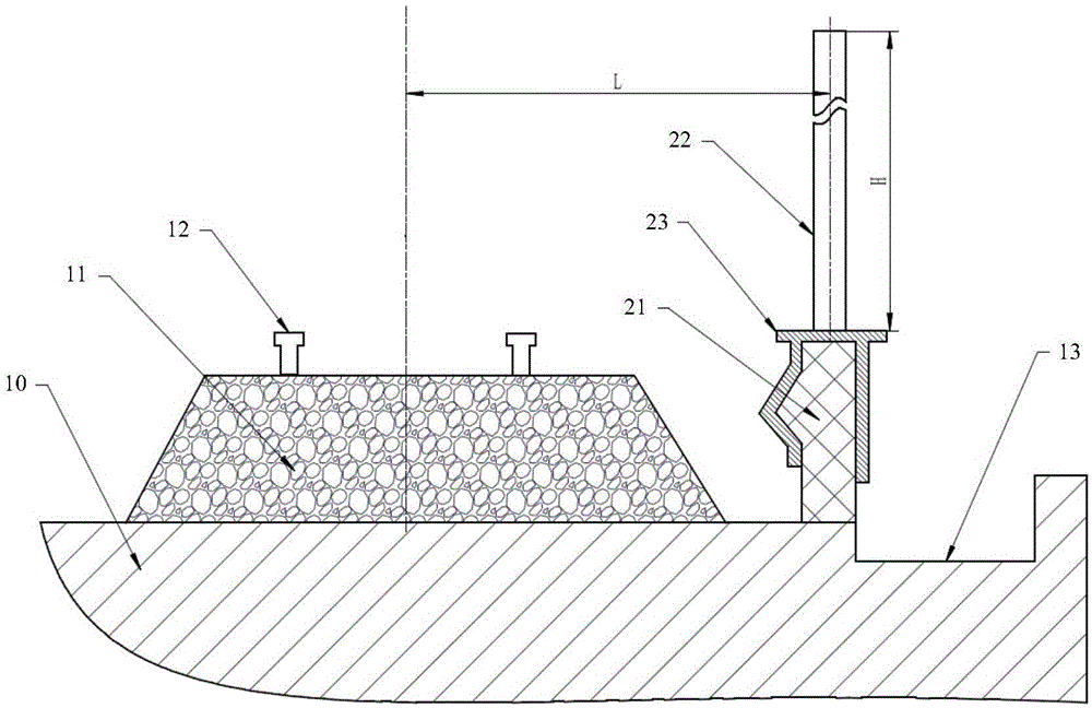
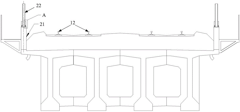
[0047] image 3 It is a schematic diagram of the T-beam near-rail noise reduction device in the first embodiment of the present invention. Figure 4 for image 3 The partial enlarged view of part A is a schematic diagram of the connection between the sound barrier and the ballast retaining wall in the first embodiment of the present invention. Such as image 3 and Figure 4 As shown, preferably, in a specific embodiment of the present invention, the sound barrier 22 installed above the ballast retaining wall 21 is connected to the ballast retaining wall 21 through anchor bolts.
[0048] Furthermore, preferably, in a specific embodiment of the present invention, the bottom of the sound barrier 22 is provided with a steel plate 23, and the bottom of the steel plate 23 is connected to the ballast retaining wall 21 through anchor bolts.
[0049] Preferably, in a specific embodiment of the ...
no. 2 example
[0051] Embodiment 2: The sound barrier is installed on the side of the ballast retaining wall facing the roadbed.
[0052] Figure 5 It is a schematic diagram of the T-beam near-rail noise reduction device in the second embodiment of the present invention. Figure 6 for Figure 5 The partial enlarged view of part A is a schematic diagram of the connection between the sound barrier and the ballast retaining wall in the second embodiment of the present invention. Such as Figure 5 and Figure 6 As shown, preferably, in a specific embodiment of the present invention, the sound barrier 22 installed on the side of the ballast retaining wall 21 facing the roadbed 11 is connected to the ballast retaining wall 21 through anchor bolts.
[0053] Further, preferably, in a specific embodiment of the present invention, steel plates 60 are provided on both sides of the ballast retaining wall 21, and the anchor bolts pass through the ballast retaining wall 21 and the steel plates 60 to c...
no. 3 example
[0055] Embodiment 3: The sound barrier is installed on the side of the ballast retaining wall facing the roadbed.
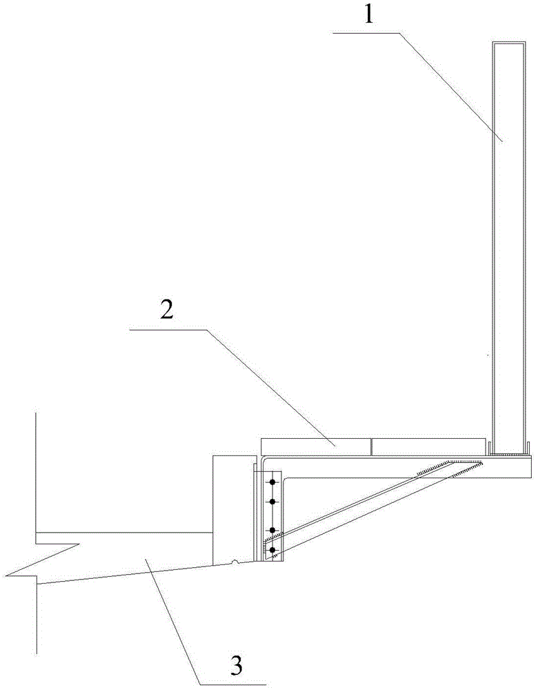
[0056] Figure 7 It is a schematic diagram of the T-beam near-rail noise reduction device in the third embodiment of the present invention. Figure 8 for Figure 7The partial enlarged view of part A is a schematic diagram of the connection between the sound barrier and the ballast retaining wall in the third embodiment of the present invention. Such as Figure 7 and Figure 8 As shown, preferably, in a specific embodiment of the present invention, the sound barrier 22 installed on the side of the ballast retaining wall 21 facing the roadbed 11 is connected to the bridge body below the ballast retaining wall 21 through anchor bolts. 10 side connections.
[0057] Furthermore, preferably, in a specific embodiment of the present invention, the anchor bolt passes through the sound barrier 22 and is connected to the side of the bridge body 10 below the ballast wal...
PUM
 Abstract
Description
Claims
Application Information
 - R&D
- Intellectual Property
- Life Sciences
- Materials
- Tech Scout
- Unparalleled Data Quality
- Higher Quality Content
- 60% Fewer Hallucinations
Browse by: Latest US Patents, China's latest patents, Technical Efficacy Thesaurus, Application Domain, Technology Topic, Popular Technical Reports.
© 2025 PatSnap. All rights reserved.Legal|Privacy policy|Modern Slavery Act Transparency Statement|Sitemap|About US| Contact US: help@patsnap.com