Eureka AIR delivers breakthrough ideas for toughest innovation challenges, trusted by R&D personnel around the world.

Guardrail capable of inclining

A technology of guardrails and cables, applied in the field of dumpable guardrails, which can solve the problems of short service life, overall guardrail damage, collision, etc.

Inactive Publication Date: 2015-11-18
孟国华
View PDF5 Cites 4 Cited by
  • Summary
  • Abstract
  • Description
  • Claims
  • Application Information

AI Technical Summary

Problems solved by technology

[0002] In the existing guardrail structure, the isolation column is usually directly fixed on the road surface. When the isolation column of this structure is subjected to external force, it is usually directly displaced or broken under the action of the external force, and the displacement causes the isolation column to break down. If it is dislocated, it cannot continue to play the role of isolation guide; if it is broken, it needs to be replaced, and its service life is short; at the same time, the isolation columns are rigidly fixedly connected to each other, and the damage will affect the entire guardrail when an external force collides , resulting in a part of the collision, causing damage to the overall guardrail

Method used


Image

  • Guardrail capable of inclining
  • Guardrail capable of inclining
  • Guardrail capable of inclining

Examples


Embodiment 1

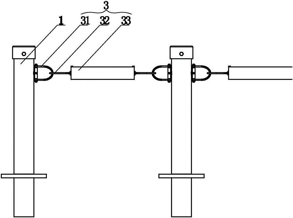
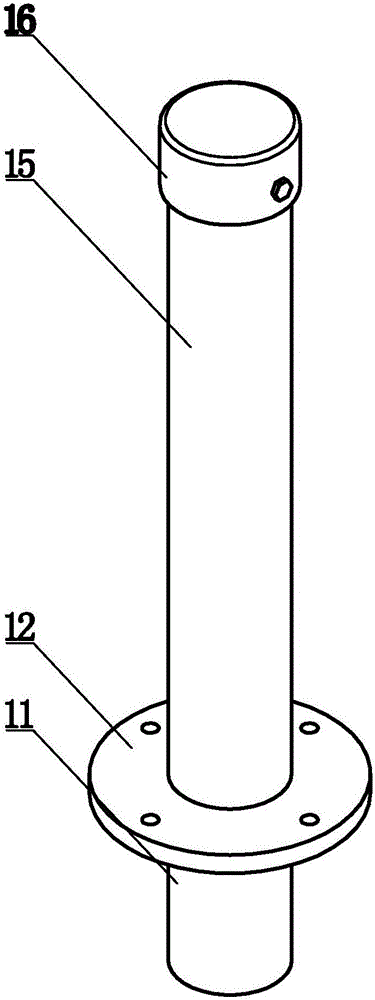
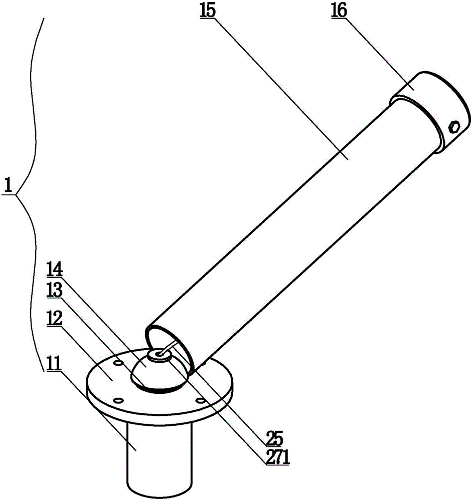
[0030] The dumpable guardrail of this embodiment, combined with figure 1 , figure 2 , image 3 and Figure 4, consisting of an isolation column 1, an adjustment mechanism 2 and a connector 3, wherein the isolation column 1 is composed of a column foot 11, a limit groove 13, a hemisphere 14, a column cylinder 15 and a column cover 16, and an abutment is set above the column foot 11 12. A hemisphere 14 is set above the base 12, and a limit groove 13 is set at the connection between the hemisphere 14 and the base 12, and the limit groove 13 is set around the lower bottom surface of the hemisphere 14; the adjustment mechanism 2 is located on the cylinder 15, including hanging beam 21, spring 22, limit frame 23, spacer 24, adjusting cable 25, limit block 26, adjusting block 27, fixed ball 28 and upper fixed block 29, and hanging beam 21 two ends are fixed on column On the upper part of the inner side of the tube 15, the upper end of the spring 22 is connected with the hanging b...

Embodiment 2

[0036] The setting and working principle of this embodiment are the same as that of Embodiment 1, the difference is that a pulley is set at the hanging beam 21, the lower end of the spring 22 is fixed on the edge of the perforation 241 of the spacer 24, and the adjusting cable 25 passes through the perforation 241 Finally, the pulley is upwardly circled through the middle part of the spring 22, and the upper fixed block 29 on the adjustable cable 25 after the circuit is connected downward with the upper end of the spring 22. This way can extend the length of the running path of the adjustable cable 25, thereby as far as possible Alleviate the effect of external force.

Embodiment 3

[0038] The setting and working principle of this embodiment are the same as that of Embodiment 1, the difference is that the gasket 24 can be fixed in the cylinder 15 by thread or electric welding, and the setting of the limit frame 23 can be omitted in this way, and the overall structure is simpler , Easy assembly.


PUM


Abstract

The invention relates to a guardrail capable of inclining, and belongs to the technical field of traffic facilities. The guardrail consists of a separation column, a regulating mechanism and a connecting component, wherein the separation column consists of four parts of a column foot, a base, a column barrel and a column cover; the base is arranged on the column foot, a hemispheric body is arranged on the base, and a limiting groove is formed between the hemispheric body and the base; the regulating mechanism is positioned in the column barrel and comprises a spring, a regulating cable, a limiting block, an upper fixing block, a regulating block and a fixing ball, the spring is hung under a hanging beam in a buckling manner, a spacer is arranged at the lower end of the spring, the limiting block is mounted on the regulating cable in a sleeving manner, the regulating block is connected to the lower end of the regulating cable, and the fixing ball is fixed at the tail end of the regulating block; the tail end of the regulating cable is fixedly connected with the hemispheric body through the regulating block and the fixing ball, and then semi-moving connection between the column barrel and the base is realized through the interaction among the spring, the spacer and the limiting block and the regulating cable, the regulating block, the fixing ball and the hemispheric body. The guardrail disclosed by the invention can be applied to traffic routes and has the advantages of high safety, good practicality and the like.

Description

technical field [0001] The invention relates to a pourable guardrail, which belongs to the technical field of traffic facilities. Background technique [0002] In the existing guardrail structure, the isolation column is usually directly fixed on the road surface. When the isolation column of this structure is subjected to external force, it is usually directly displaced or broken under the action of external force, and the displacement causes the isolation column to break down. Misalignment, and cannot continue to play the role of isolation guide; the broken ones need to be replaced, and the service life is short; at the same time, the isolation columns are rigidly fixedly connected to each other. When the external force collides, this damage will affect the entire guardrail , resulting in a part of the collision, causing damage to the overall guardrail. [0003] Based on this, this application is made. Contents of the invention [0004] In order to overcome the above-m...

Claims


Application Information

Patent Timeline
IPC IPC(8): E01F15/02
Inventor 孟国华孟思恬
Owner 孟国华
Why Eureka
Eureka Blog
Learn More