
Self heat-insulation system of cast-in-situ concrete shear wall and method for manufacturing self heat-insulation system

A concrete shear wall and self-insulation technology, applied in the direction of insulation, walls, building components, etc., can solve the problem that the design size of the outer protective layer of the wall cannot be accurately controlled, the quality of the cast-in-place reinforced concrete wall is affected, and there is no good solution. methods, etc., to achieve the effect of improving the thermal insulation function, ensuring quality, and achieving precise control.

Active Publication Date: 2015-11-18
王惠滨
View PDF10 Cites 5 Cited by
  • Summary
  • Abstract
  • Description
  • Claims
  • Application Information

AI Technical Summary

Problems solved by technology

[0002] At present, in the construction process of cast-in-place reinforced concrete frame-shear structure exterior walls, the thermal insulation system mostly uses inner and outer double-layer steel wire mesh. On the one hand, the wall insulation skeleton and the oblique web wires are connected to the shear wall reinforcement through the inner steel wire mesh. During construction, about 100 oblique web wires are needed per square meter. Since the abdominal wires are made of metal heat-conducting materials, the It will affect the thermal insulation performance of the wall to a certain extent.
Nowadays, the state requires that the energy-saving emission reduction index be increased from 65% to 75%, but according to the current mature construction technology, it is difficult to complete this new energy-saving emission reduction index
[0003] Moreover, in the current construction process of cast-in-place reinforced concrete shear walls, since the design size of the outer protective layer of the wall cannot be precisely controlled, it will lead to leakage, cracking, and swelling of the wall after the formwork is removed, which will affect the construction quality. problem, which seriously affects the quality of cast-in-place reinforced concrete walls, and there is no good solution to this problem

Method used


Image

  • Self heat-insulation system of cast-in-situ concrete shear wall and method for manufacturing self heat-insulation system
  • Self heat-insulation system of cast-in-situ concrete shear wall and method for manufacturing self heat-insulation system
  • Self heat-insulation system of cast-in-situ concrete shear wall and method for manufacturing self heat-insulation system

Examples


Embodiment 1

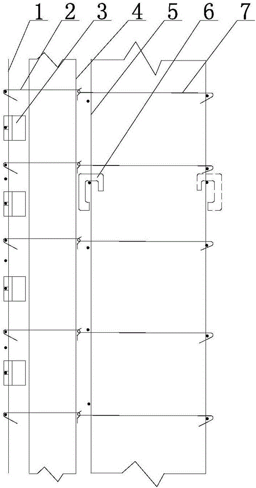
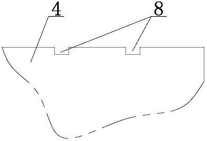
[0024] Such as figure 1 As shown, the cast-in-place concrete shear wall self-insulation system includes the outer steel wire mesh 1 and the insulation board 4, the insulation board 4 is a multi-layer multi-cavity hollow board made of PVC material, and the outer steel wire mesh 1 and the insulation board 4 Install a number of multi-functional CL network frame board protective layer mortar pads 3 and connect them through a number of insulation board fixing clips 2. The inner end of the insulation board fixing clip 2 is hook-shaped, and the outer end is straight from the inside to the outside The plate 4 is passed through, and the buckle is bent and welded on the horizontal wire of the outer steel wire mesh sheet 1. The middle section of the hook shape has a hook, and the end is a vertical edge. The vertical edge is in line with the above-mentioned multi-layer multi-cavity The hollow boards are clamped tightly together; a number of multi-functional reinforcement protection layer ...

Embodiment 2

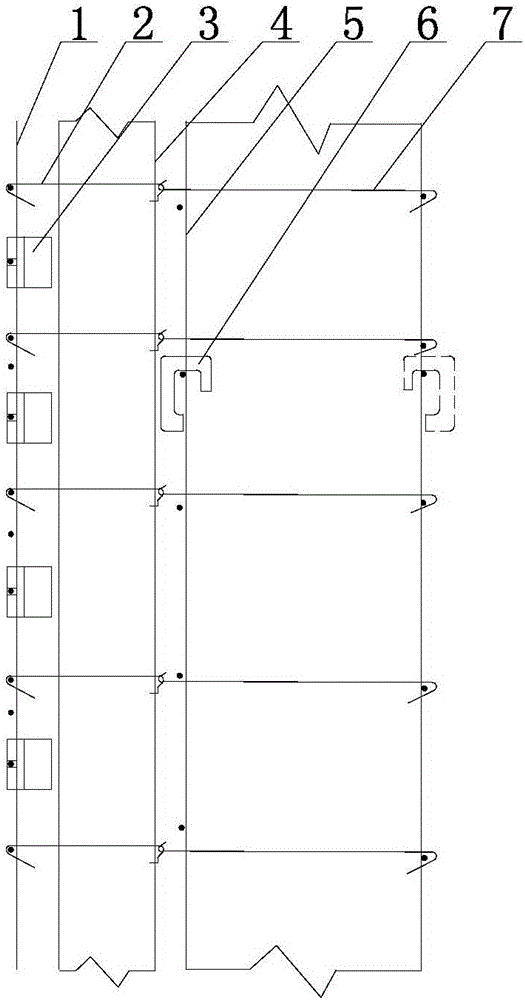
[0033] Such as figure 2 As shown, the XPS extruded board or EPS foam board is selected as the insulation board 4, but since the XPS extruded board or EPS foam board is easily penetrated by steel wires, the hook-shaped end of the insulation board fixing clip 2 in this embodiment The design is L-shaped, the vertical side of the L-shaped board is tightly attached to the XPS extruded board or EPS foam board, and the horizontal side of the L-shaped board is inserted into the XPS extruded board or EPS foam board. 4 reliable fixation. Other structures of this embodiment are the same as those of Embodiment 1.


PUM


Abstract

The invention belongs to the field of buildings, and particularly relates to a self heat-insulation system of a cast-in-situ concrete shear wall and a method for manufacturing the self heat-insulation system. The self heat-insulation system comprises an outer-side steel wire mesh and a heat-insulation plate. A plurality of multifunctional CL net frame plate protective layer mortar spacers are mounted between the outer-side steel wire mesh and the heat-insulation plate and are connected with the outer-side steel wire mesh and the heat-insulation plate by a plurality of heat-insulation plate fixing clamp components, the heat-insulation plate fixing clamp components are provided with bent inner ends, straight heads at the outer ends of the heat-insulation plate fixing clamp components penetrate the heat-insulation plate from the inside to the outside, are bent and hasped on transverse wires of the outer-side steel wire mesh and are welded with the transverse wires, bent middle sections of the heat-insulation plate fixing clamp components are provided with hooks, and the heat-insulation plate is clamped at the tail ends of the heat-insulation plate fixing clamp component; a plurality of multifunctional reinforcing steel bar protective layer spacers are mounted between the heat-insulation plate and a reinforcing steel bar of the shear wall and are connected with the heat-insulation plate and the reinforcing steel bar of the shear wall by a plurality of connecting clamp components, one end of each connecting clamp component is bent and is hooked in the hook at the inner end of the corresponding heat-insulation plate fixing clamp component, the other end of each connecting clamp component is bent, and the reinforcing steel bar of the shear wall is tightly hooked by the other end of each connecting clamp component. The self heat-insulation system and the method have the advantages that the cost of a building can be reduced, the heat-insulation performance of a wall body of the building can be improved, and the quality of the cast-in-situ reinforced concrete wall body can be guaranteed.

Description

technical field [0001] The invention relates to a cast-in-situ concrete shear wall self-insulation system and a manufacturing method thereof, belonging to the construction field. Background technique [0002] At present, in the construction process of cast-in-place reinforced concrete frame-shear structure exterior walls, the thermal insulation system mostly uses inner and outer double-layer steel wire mesh. On the one hand, the wall insulation skeleton and the oblique web wires are connected to the shear wall reinforcement through the inner steel wire mesh. During construction, about 100 oblique web wires are needed per square meter. Since the abdominal wires are made of metal heat-conducting materials, the It will affect the thermal insulation performance of the wall to a certain extent. Nowadays, the state requires that the energy-saving emission reduction index be increased from 65% to 75%, but according to the current mature construction technology, it is difficult to ...

Claims


Application Information

Patent Timeline
Patent Type & Authority Applications(China)
IPC IPC(8): E04B2/00E04B2/84E04B1/80
Inventor 王惠滨王凯王磊
Owner 王惠滨
Learn More