
Improved screw-in type back bolt and connection structure

A technology for connecting structures and back bolts, which is applied to building components, building structures, coverings/linings, etc. It can solve problems such as high cost, bending and slipping out of the head, bending and breaking of pieces, etc., and achieves strong earthquake resistance and good fit Effect

Inactive Publication Date: 2015-11-18
HANGZHOU STAN NEW MATERIALS TECH CO LTD
View PDF5 Cites 3 Cited by
  • Summary
  • Abstract
  • Description
  • Claims
  • Application Information

AI Technical Summary

Problems solved by technology

[0002] At present, the existing screw-in back bolt used in the curtain wall of the building envelope structure has the biggest advantage that the circle on the head of the expansion part and the bottom expansion hole drilled on the back of the stone plate, porcelain plate, etc. form a full circle of synchronous load bearing. The biggest disadvantage is that the bearing capacity of the expansion piece is too weak
The main reason is to rely on the force of the thread screwed into the screw to expand the expansion element. If it is too thick, it cannot be expanded, so the expansion element is made very thin, and its thread is only about 0.3 mm, so the sheet has poor bearing capacity. , and because the manual installation cannot control the depth of screw screwing in, once it is not screwed in to the end, it will cause indentation and pull out when bearing negative wind pressure. Wear, and the screw will loosen under the vibration frequency of positive and negative wind pressure of 200,000 to 300,000 times per year, so it can only be applied indoors. If it is applied to the outer curtain wall, the hidden danger is relatively large and the cost is high. In order to prevent thinner It cannot be tapped or demolded. It adopts a hexagonal nut + a thicker long tube through hot heading first. After tapping, except for the expansion head, the entire section is cut off from the outside. After cutting the expansion piece groove Descaling of the secondary tapping, because it is too thin, the amount of waste and defective products is large during the secondary tapping and polishing. For the production of fasteners, it is easy to escape the detection of waste and defective products, which will cause serious troubles
When installing the pendant to tighten the nut, because the screw rotates with the nut, almost 100% of it is against the bottom of the board, so there is a greater hidden danger
[0003] In order to solve the limit, there is another screw-in back bolt, which adopts a limit flange at the bottom of the inner hole. On the surface, it solves the limit, but it has made a serious mistake from the mechanical professional point of view, because the screw The load-bearing of the in-type back bolt mainly depends on the threads on the expansion piece to transmit the load-bearing capacity to the screw through the threads on the screw.
However, because the limit flange is set at the bottom of the hole for thread tapping, at least the load-bearing section cannot pass the force through the thread, and this place is just the key load-bearing place of the expansion head, so it can only rely on the bottom of the thread as thin as a sheet of paper. The 4 pieces bear the load, once the expansion head bears the force, the piece will bend and break and the head will bend and slide out, that is, it cannot bear the heavy load tension of the stone plate and the tension of positive and negative wind pressure
[0004] In addition, with the soaring labor costs in our country and the impact of the construction industry on the tighter and tighter construction period, our country is entering the era of machines replacing labor in an all-round way, and the existing screw-in back bolts are not only complicated in production process, but also pre-installed and The installation process is more complicated, labor-intensive and time-consuming, and automatic installation cannot be used

Method used


Image

  • Improved screw-in type back bolt and connection structure
  • Improved screw-in type back bolt and connection structure
  • Improved screw-in type back bolt and connection structure

Examples


Embodiment Construction

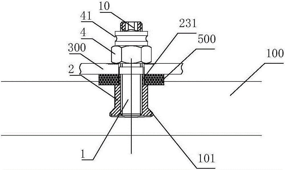
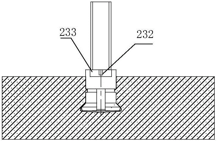
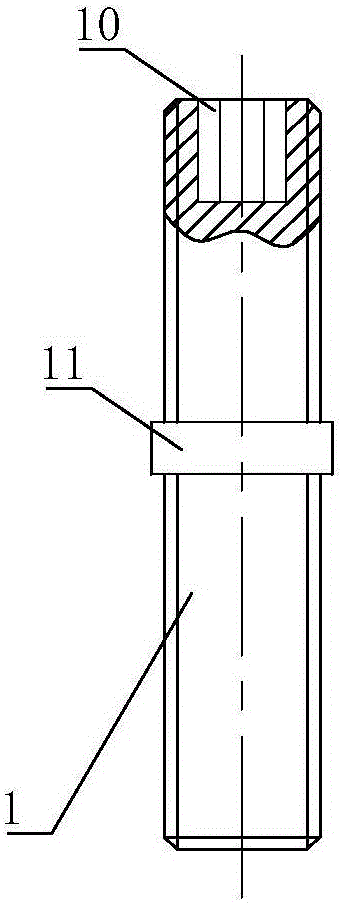
[0033] Refer to attached figure 1 , 2 , 5, 6. The screw-in back bolt provided by the present invention includes a screw rod 1 and an expansion element 2. The expansion element has a cylindrical body 21 and a plurality of expansion parts 22 at one end of the cylindrical body. The expansion element is provided with an internal thread, so The screw rod 1 and the internal thread of the expansion element 2 are screwed together.

[0034] The expansion part 22 may adopt a sheet shape. The inner side of the expansion part 22 has a force-bearing part 221 cooperating with the screw rod, and the force-bearing part 221 may be a threaded surface threadedly connected with the screw rod. The expansion part 22 is provided with a protruding part 222, and the protruding part 222 is used as a force receiving part to cooperate with the cone part 102 of the bottom expansion hole 101 after the expansion part 22 is expanded, and the screw rod 1 is passed through the In the expansion element 2 , ...


PUM


Abstract

The invention provides an improved screw-in type back bolt and a connection structure. The back bolt comprises a screw and an expanding element, wherein the screw is provided with a connector which can be connected with an electric or pneumatic mounting tool; a projection is arranged on an extending portion at one end of the expanding element; a positioning portion is arranged at the other end of the expanding element and is provided with a weak portion which can be broken by the electric or pneumatic mounting tool when the screw rotates to a limited position; and after being broken, the weak portion is in matched connection with the screw so as to prevent the screw from rotating relative to the expanding element, and the screw and the expanding element form a whole body and cannot rotate relative to each other. By the back bolt, mounting automation control can be convenient to implement; the percent of contact areas of the back bolt and a bottom-extending aperture is high, and a limiting structure on the bottom of the bottom-extending aperture is not required; and an integral and perpetual connection structure can be implemented, stress of the expanding portion can be minimized and even zero, strong earthquake and subway starting and stopping impact can be resisted, and welding reinforcement is not required.

Description

technical field [0001] The invention relates to a back bolt, which is used for the decoration of dry-hanging boards of various buildings. It is anchored and connected through the back of the board, so it is called "back bolt". It is used for dry-hanging curtain walls such as subway stations, especially for porcelain plates and glass-ceramics. The invention also relates to connection structures utilizing such back bolts. Background technique [0002] At present, the existing screw-in back bolt used in the curtain wall of the building envelope structure has the biggest advantage that the circle on the head of the expansion part and the bottom expansion hole drilled on the back of the stone plate, porcelain plate, etc. form a full circle of synchronous load bearing. The biggest disadvantage is that the bearing force of the expansion piece is too weak. The main reason is to rely on the force of the thread screwed into the screw to expand the expansion element. If it is too thi...

Claims


Application Information

Patent Timeline
Patent Type & Authority Applications(China)
IPC IPC(8): E04B2/88E04F13/24
Inventor 徐跃华徐洁媛
Owner HANGZHOU STAN NEW MATERIALS TECH CO LTD
Learn More