Noiseless fan facilitating heat dissipation

A quiet and convenient technology, which is applied to components, instruments, and electrical digital data processing of elastic fluid pumping devices to achieve improved heat dissipation, low noise, and good heat dissipation

Inactive Publication Date: 2015-11-18
成都思邦力克科技有限公司
View PDF5 Cites 0 Cited by
  • Summary
  • Abstract
  • Description
  • Claims
  • Application Information

AI Technical Summary

Problems solved by technology

[0003] The present invention overcomes the deficiencies of the prior art and provides a silent fan that is convenient for heat dissipation. The fan has low noise under the premise of ensuring the air volume and pressure of the fan.

Method used


Image

  • Noiseless fan facilitating heat dissipation

Examples


Embodiment 1

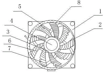
[0016] Such as figure 1 As shown, the present invention includes a stator 4 and a rotor, and the stator 4 includes a bearing, a coil and a circuit board, and multi-turn coils are wound on the bearing, and the bearing is vertically installed on the top of the circuit board; the rotor includes a plurality of fan blades 2, The ring magnet 3 and the shaft are evenly arranged on the surface of each fan blade 2 along the counterclockwise flow guide line 6, the ring magnet 3 is sleeved on the shaft, and a cavity is formed between the ring magnet 3 and the shaft, and the bearing and The central hole of the circuit board is set on the shaft, and a rubber sleeve is also sleeved outside the ring magnet 3. On the side of the rubber sleeve, there is a circle of fan blades 2 evenly radiating. The fan blades form an acute angle with the vertical direction. The entire stator 4 and The rotors are installed in the circular cavity formed by the base 1, and a circular ring is installed on the inn...

Embodiment 2

[0019] This embodiment is preferably as follows on the basis of Embodiment 1: In order to facilitate the addition of heat exchange fluid and the discharge of heat exchange fluid with a high temperature, an inlet for adding liquid is also provided on the side wall of the circular circle. The bottom also is provided with the outlet that puts liquid.

[0020] The heat exchange liquid 8 is an aqueous solution.

[0021] A plurality of notches 7 are provided on one side of each fan blade 2 , and each notch 7 has a V-shaped structure. The design of the notch can quickly divert part of the wind pressure while ensuring the same air volume, reducing the large noise generated by the friction between wind pressure and air.

[0022] The ends of a ring of fan blades 2 uniformly radiating on the side of the rubber sleeve are all deflected counterclockwise, and the width of each fan blade 2 is between 8-15 cm. It can make each fan blade contact with more air area, and more airflow can pass ...


PUM


Abstract

The invention discloses a noiseless fan facilitating heat dissipation. The noiseless fan comprises a stator and a rotor. The stator comprises a bearing, a coil and a circuit board. A plurality of circles of coil bodies are wound on the bearing, and the bearing is vertically installed on the top of the circuit board. The rotor comprises a plurality of fan blades, an annular magnet and a shaft. Flow guiding lines in the anticlockwise direction are evenly arranged on the surfaces of the fan blades. The annular magnet is arranged on the shaft in a sleeving manner. A cavity is formed between the annular magnet and the shaft. A center hole of the bearing and a center hole of the circuit board are formed in the shaft in a sleeving manner. The annular magnet is sleeved with a rubber sleeve. A circle of fan blades are evenly arranged on the side face of the rubber sleeve in a radiation manner. The acute angle is formed between the fan blades and the vertical direction. The whole stator and the whole rotor are both installed in a circular cavity formed by a base. A round ring is installed on the inner wall of the circular cavity formed by the base. By means of the structure, under the premise that the air volume and the air pressure of the fan are guaranteed, noise is low, the temperature of the fan is not prone to being overhigh even if the fan runs for a long term, and the heat dissipation effect is better.

Description

technical field [0001] The invention relates to the field of computer heat dissipation, in particular to a silent fan which is convenient for heat dissipation. Background technique [0002] The working principle of the fan is simply that the current passes through the control circuit to generate a rotating magnetic field at the stator coil and the electromagnet, pushing the magnet on the rotor to rotate in a specific direction, thereby driving the entire fan blade to rotate at a high speed, and pushing the air to quickly flow from the fan blade Pass through, has reached a specific air volume and air pressure. However, air volume and air pressure are the two most important performance parameters of the fan, and the air pressure mentioned here is the pressure of the wind. The greater the air pressure, the greater the force of the wind, and it is easier to punch the case, The dust filter and other components are blown through; the air volume can be understood as the amount of ...

Claims


Application Information

Patent Timeline
IPC IPC(8): F04D25/08F04D29/66F04D29/58F04D29/26G06F1/20
Inventor 罗庆罗世培聂龙华沈军叶富强刘刚庞平
Owner 成都思邦力克科技有限公司
Why Eureka
Try Eureka