Device and method for quickly detecting air leakage of ultraviolet germicidal lamp

A technology of ultraviolet light and germicidal lamps, which is applied in the field of inspection, can solve the problems of unreliable inspection methods and long cycle times, achieve the effects of shortening the production cycle, solving lamp tube leakage, and improving quality reliability

Inactive Publication Date: 2015-11-18
宁波大榭开发区佑威光电有限公司
View PDF5 Cites 2 Cited by
  • Summary
  • Abstract
  • Description
  • Claims
  • Application Information

AI Technical Summary

Problems solved by technology

Usually, in order to better check the leakage of the lamp tube, the manufacturer prepares the lamp tube in advance, and then stores the lamp tube. The general storage period is 15 days or even longer, and then checks the leak of the lamp tube. It takes a long time to test the leaking lamp tube, and the inspection method is unreliable. To a certain extent, it also brings more troubles to the lamp tube manufacturer.

Method used


Image

  • Device and method for quickly detecting air leakage of ultraviolet germicidal lamp

Examples


Embodiment 1

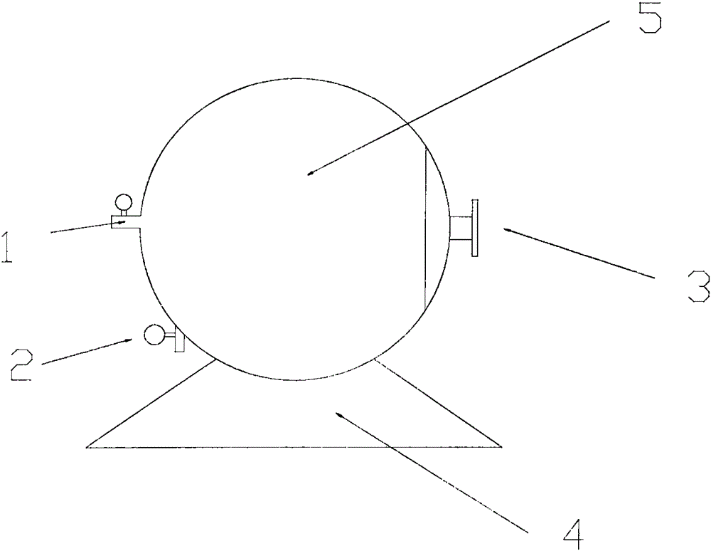
[0027] The structure of this embodiment, such as figure 1 , one A device for quickly checking air leakage of ultraviolet germicidal lamps, the device for quickly checking air leakage of ultraviolet germicidal lamps is a hyperbaric cabin body 5, the hyperbaric cabin body 5 is located on the cabin body support platform 4, and the hyperbaric cabin body 5 is provided with There are high-pressure cabin door 3, in-cabin pressurization valve 1, pressure-stabilizing and pressure-relieving valve 2. The setting of the hyperbaric cabin body 3 of the present invention mainly serves to facilitate the placement of the lamp tube to be tested, and to realize the enhancement of the pressure difference between the inside and the outside of the lamp tube, thereby facilitating rapid inspection of air leakage; the setting of the cabin body support platform 4 in the present invention , mainly to facilitate the support of the high-pressure cabin body 5; wherein the role of the booster valve 1 in t...

Embodiment 2

[0029] On the basis of Embodiment 1, this embodiment further defines that the hyperbaric cabin body 5 is a spherical hyperbaric cabin, and here the shape of the hyperbaric cabin body 5 is limited, preferably a spherical hyperbaric cabin, and the cabin body support platform 4 The shape of the upper end matches the shape of the hyperbaric cabin body 5. The upper end of the cabin support platform 4 is a circular arc end, and other parts in this embodiment are the same as those in Embodiment 1, and will not be repeated here.

Embodiment 3

[0031] On the basis of the above-mentioned embodiments, this embodiment further defines that the in-cabin booster valve 1 and the pressure-stabilizing and pressure-relieving valve 2 are set on the same side of the high-pressure cabin body 5, and the in-cabin boosting valve 1 is located at the pressure-stabilizing and releasing valve. Press the upper end of valve 2. Here, the positional relationship between the pressure-increasing valve 1 and the pressure-stabilizing and releasing valve 2 in the cabin is limited, mainly for the convenience of operation and the taking out and putting in of the lamp tube to be tested. Other parts in this embodiment are the same as those in the foregoing embodiment, and will not be repeated here.


PUM


Abstract

The present invention discloses a device and a method for quickly detecting the air leakage of an ultraviolet germicidal lamp. The device for quickly detecting the air leakage of the ultraviolet germicidal lamp is composed of a high-pressure cabin body and the high-pressure cabin body is arranged on a cabin body bracket bench. The high-pressure cabin body is provided with a high-pressure cabin door, a cabin pressurization valve and a steady-pressure decompression valve. The method specifically comprises the steps of vacuumizing a to-be-tested lamp tube, and hermetically filling the inert gas inside the lamp tube; 2) placing the above lamp tube processed in the step 1) in the high-pressure cabin body, connecting the high-pressure cabin body with a pressurization pump, and switching on the cabin pressurization valve to pressurize the high-pressure cabin body; 3) switching on the steady-pressure decompression valve to take the to-be-tested lamp tube out of the high-pressure cabin body when the air pressure outside the to-be-tested lamp tube is 300-600 times the air pressure inside the to-be-tested lamp tube; 4) detecting the to-be-tested lamp tube by means of a high-frequency spark leak detector. The device is simple in operation method and greatly shortens the manufacturing cycle. Meanwhile, the quality reliability of products is improved. The air-leakage problem of lamp tubes in the lamp manufacturing industry can be solved.

Description

technical field [0001] The invention relates to the technical field of inspection, in particular to a device and method for rapidly inspecting air leakage of an ultraviolet germicidal lamp. Background technique [0002] The lamp tube sealed with quartz glass and molybdenum sheet will inevitably encounter the problem of slow leakage of the lamp tube in the production and manufacture, that is, the chronic leakage of the lamp tube. After a period of time, the gas in the lamp tube will leak to the point where the lamp tube cannot take off and ignite. , and even the gas leaks out. Therefore, many manufacturers have conducted research on the problem of lamp tube leakage, and have taken relevant measures. Usually, in order to better check the leakage of the lamp tube, the manufacturer prepares the lamp tube in advance, and then stores the lamp tube. The general storage period is 15 days or even longer, and then checks the leak of the lamp tube. It takes a long time to test the le...

Claims


Application Information

Patent Timeline
Patent Type & Authority Applications(China)
IPC IPC(8): G01M3/40
Inventor 刘忠强吴琼
Owner 宁波大榭开发区佑威光电有限公司
Why Eureka
Try Eureka