Precision displacement driven feed mechanism and its combination, tool

A driving feed, precision displacement technology, applied in the field of machining, can solve the problems of inability to meet the needs of precision control and processing, inconvenient driving force and driving force control and adjustment, complex structure and installation, etc., to achieve light weight and simple structure. , the effect of strong movement stability

Active Publication Date: 2018-02-16
伶机(上海)驱动技术中心(有限合伙)
View PDF5 Cites 0 Cited by
  • Summary
  • Abstract
  • Description
  • Claims
  • Application Information

AI Technical Summary

Problems solved by technology

[0003] 1. Insufficient driving force;
[0004] 2. Complex structure installation;
[0005] 3. It is not convenient to adjust the driving force and driving force control according to the needs;
[0006] Due to the above defects, the existing displacement feed mechanism usually cannot meet the needs of modern industry for precision control and processing

Method used


Image

  • Precision displacement driven feed mechanism and its combination, tool
  • Precision displacement driven feed mechanism and its combination, tool
  • Precision displacement driven feed mechanism and its combination, tool

Examples


Embodiment 1

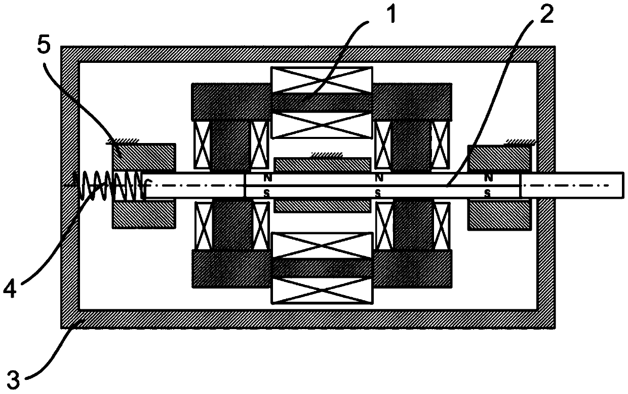
[0051] like figure 1 As shown, this embodiment provides a precision displacement drive feeding mechanism, including a driving body and a moving body, a magnetic control circuit is formed between the driving body and the moving body, and the magnetic pole direction of the moving body is related to the surface of the moving body. (The surface with the largest surface area) is vertical, and the moving body moves under the action of the magnetron force of the driving body.

[0052] Further, the driving body includes two groups of electromagnets, wherein each group of electromagnets includes two groups of electromagnetic coils and a conduction coil connected between the two groups of electromagnetic coils, the electromagnet and the N pole of the moving body and the A control loop is formed between the S machines; two sets of electromagnets are symmetrically arranged on both sides of the moving body.

[0053] Further, both the electromagnetic coil and the conduction coil include an...

Embodiment 2

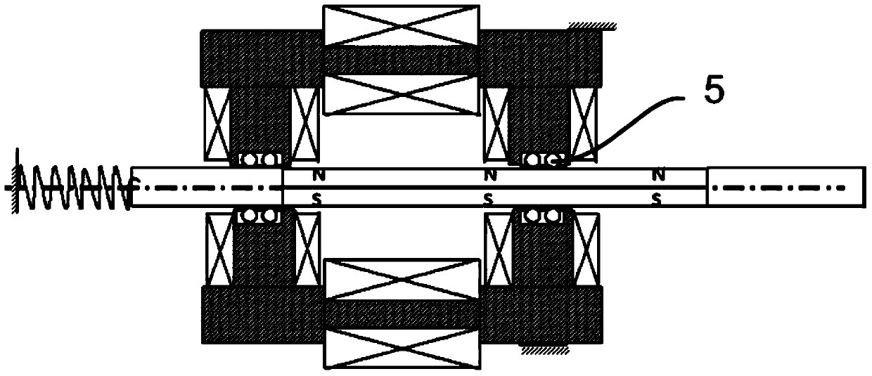
[0065] like image 3 As shown, this embodiment is a modification of Embodiment 1, and the difference from Embodiment 1 is that the guiding mechanism provided in this embodiment is disposed between the iron core of the electromagnetic coil and the moving body.

[0066] The working principle of this embodiment is the same as that of the embodiment, and details are not repeated here.

Embodiment 3

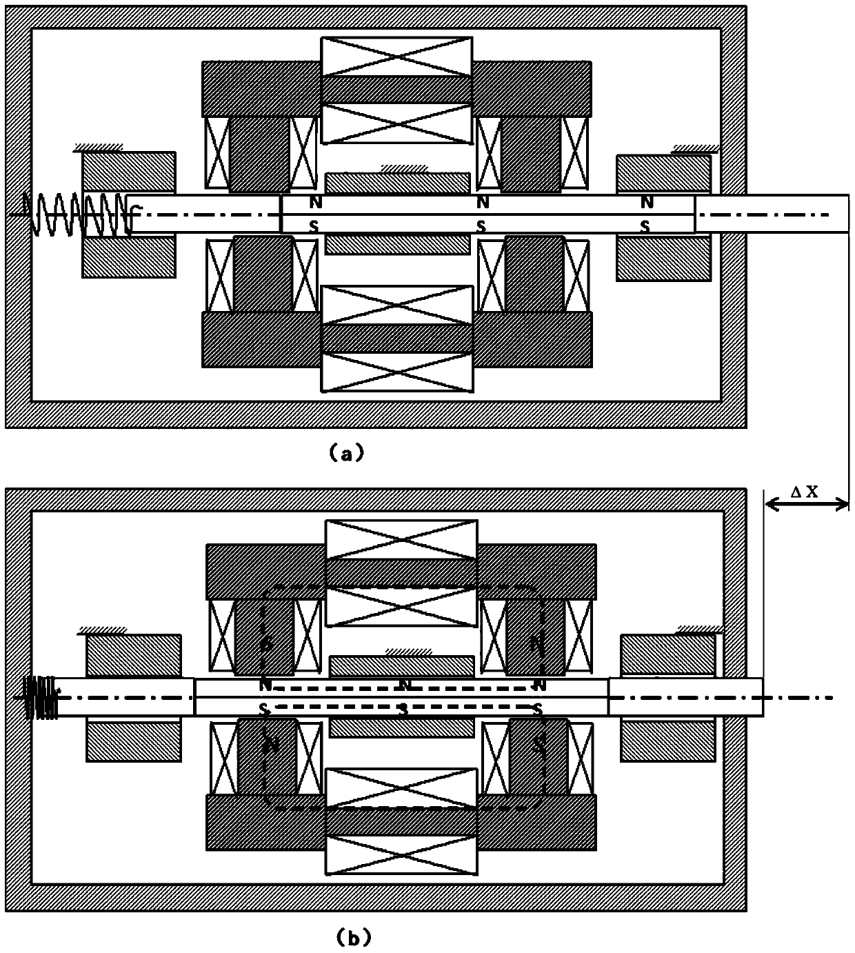
[0068] like Figure 4 As shown, this embodiment is a modification of Embodiment 2, and the difference from Embodiment 2 is that the electromagnet provided in this embodiment is a set, which is arranged on one side of the moving body, and the return spring is eliminated.

[0069] like Figure 5 (a) to Figure 5 As shown in (c), in this embodiment, a magnetic control loop is formed between the electromagnetic coil and the S pole (or N pole) of the permanent magnet. In the initial state, the permanent magnet is located at the center of the electromagnet, and an alternating current is applied to the electromagnet, so that the electromagnet generates a magnetic field, and the moving body moves left and right under the repulsive force of the magnetic field.


PUM


Abstract

The present invention provides a precision displacement drive feeding mechanism, a combination thereof, and a cutter. The mechanism comprises a drive body and a moving body, a magnetic control loop is formed between the drive body and the moving body, a magnetic pole direction of the moving body is perpendicular to a surface of the moving body, the moving body moves under the action of a magnetic control force of the drive body, and control loops are formed between electromagnets and an N pole and / or an S pole of the moving body. A combined-type precision displacement drive feeding mechanism based on the precision displacement drive feeding mechanism and the cutter are also provided. The mechanism is simple in structure and light in weight, precise control of moving strokes of the moving body is realized, and requirements of the modern industry for precision control are also met.

Description

technical field [0001] The invention relates to a feeding mechanism in the technical field of machining, in particular to a precise displacement driving feeding mechanism, a combination thereof, and a cutting tool. Background technique [0002] The displacement feed mechanism is mainly used in the control of the tool in machining, and the processing depth of the tool is adjusted through the telescopic displacement of the feed mechanism. The existing displacement feeding mechanism is usually controlled by a motor. This structure leads to the following defects in the existing displacement feeding mechanism: [0003] 1. Insufficient driving force; [0004] 2. The structure and installation are complicated; [0005] 3. It is inconvenient to adjust the driving force and driving force control according to the needs; [0006] Due to the above-mentioned defects, the existing displacement feeding mechanism usually cannot meet the demands of modern industry for precise control and ...

Claims


Application Information

Patent Timeline
Patent Type & Authority Patents(China)
IPC IPC(8): G05B19/19
CPCG05B19/19
Inventor 杨斌堂
Owner 伶机(上海)驱动技术中心(有限合伙)
Why Eureka
Try Eureka