Automatic alignment method and device for unmanned plane

An automatic sensing and alignment device technology, applied in the electronic field, to achieve the effect of improving accuracy and reducing range

Active Publication Date: 2015-11-18
深圳中智卫安机器人技术有限公司
View PDF5 Cites 16 Cited by
  • Summary
  • Abstract
  • Description
  • Claims
  • Application Information

AI Technical Summary

Problems solved by technology

[0002] In recent years, unmanned aerial vehicles are mostly used for high-voltage wire inspections, and the flying tasks of unmanned aerial vehicles are mostly controlled by humans, and due to the limitation of the battery capacity of unmanned aerial vehicles, generally they can only fly for a short time. For the industry demand for autonomous inspection of high-voltage wires, the UAV autonomous charging platform came into being. During the series of processes from the detection of the power alarm to the autonomous landing of the UAV, we found that the use of wireless charging The method is economical, reliable, green and energy-saving, and will not pollute the environment, but the problem of how to make the wireless charging transmitting coil of the drone accurately perceive the receiving coil of the drone parked on the platform has not been solved.

Method used


Image

  • Automatic alignment method and device for unmanned plane
  • Automatic alignment method and device for unmanned plane
  • Automatic alignment method and device for unmanned plane

Examples


Embodiment 1

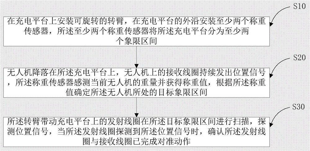
[0050] figure 1 It is a flow chart of a UAV automatic sensing alignment method provided in Embodiment 1 of the present invention.

[0051] An automatic induction alignment method for drones, which is suitable for wireless charging of drones. The charging coil includes a transmitting coil arranged on a charging platform and a receiving coil arranged on the drone, including:

[0052] S10. Install a rotatable arm on the charging platform, install at least two load cells on the outer edge of the charging platform, and at least two load cells divide the charging platform into at least two quadrants;

[0053] S20. The UAV lands on the charging platform, the receiving coil on the UAV continuously sends out position signals, the weighing sensor senses the current weight of the UAV and obtains the weighing value, and determines the position of the UAV according to the weighing value. Target quadrant interval;

[0054] S30. The rotating arm drives the transmitting coil on the charging...

Embodiment 2

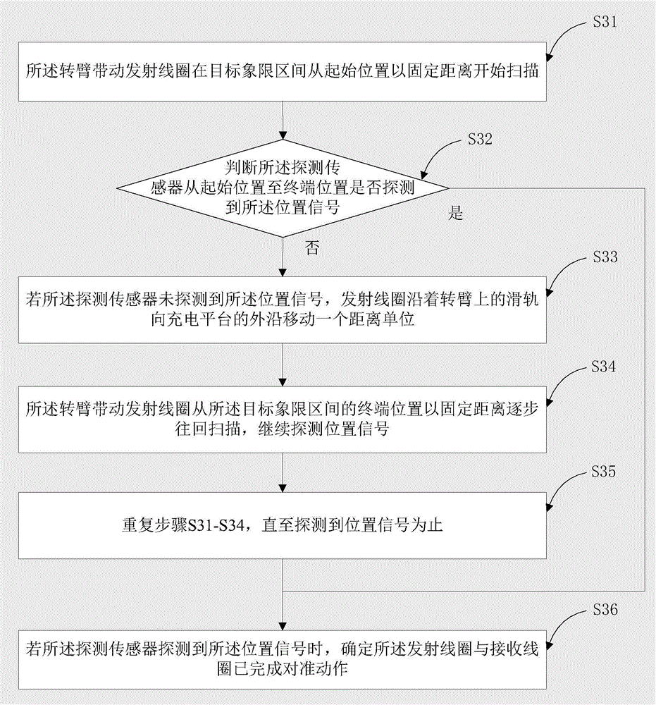
[0060] Such as figure 2 As shown, in this embodiment, step S30 includes:

[0061] S31. The rotating arm drives the transmitting coil to scan from the starting position at a fixed distance in the target quadrant;

[0062] In this embodiment, the target quadrant is a fan-shaped area, and the two sides of the fan-shaped area are respectively defined as the starting position and the terminal position, and the two are only relative.

[0063] S32. Judging whether the detection sensor has detected the position signal from the initial position to the terminal position;

[0064] S33. If the detection sensor does not detect the position signal, the transmitting coil moves along the sliding rail on the rotating arm to the outer edge of the charging platform for a distance unit;

[0065] S34. The rotating arm drives the transmitting coil to scan back step by step at a fixed distance from the terminal position of the target quadrant, and continue to detect position signals;

[0066] S3...

Embodiment 3

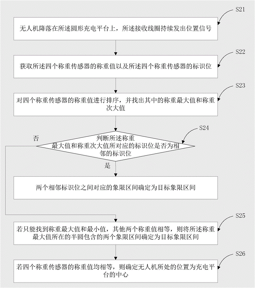
[0072] Such as image 3 As shown, in this embodiment, the number of load cells is four, and accordingly, step S20 includes:

[0073] S21. The drone lands on the charging platform, and the receiving coil continuously sends out position signals;

[0074] S22. Obtain the weighing values ​​of the four load cells and the identification bits of the four load cells;

[0075] S23. Sorting the weighing values ​​of the four load cells, and finding out the maximum weighing value and the second maximum weighing value;

[0076] S24, judge whether the identification bit corresponding to the weighing maximum value and the weighing second maximum value is an adjacent identification position, if so, the quadrant interval corresponding between the two adjacent identification positions is determined to be the target quadrant interval; if not, Then enter the following steps:

[0077] S25. If only the maximum weighing value and the minimum value can be found, and the other two weighing values ​...


PUM


Abstract

The invention relates to the technical field of electronics, and specifically relates to an automatic alignment method and device for an unmanned plane. The method comprises the steps: installing a rotating arm on a charging platform, and installing at least two weighing sensors at the outer edge of the charging platform, wherein the weighing sensors enables the charging platform to be divided into at least two quadrant sections; judging a target quadrant section where the unmanned plane is located according to the weighing values of the weighing sensors; driving a transmitting coil on the charging platform through the rotating arm to carry out scanning in the target quadrant section, detecting a position signal, and confirming that the transmitting coil and a receiving coil have already completed alignment when the transmitting coil detects the position signal. The method and device can prejudge a landing rough area of the unmanned plane, greatly reduce the scanning range of the rotating arm, and improve the precision.

Description

technical field [0001] The invention relates to the field of electronic technology, in particular to an automatic sensing alignment method and device for a drone. Background technique [0002] In recent years, unmanned aerial vehicles are mostly used for high-voltage wire inspections, and the flying tasks of unmanned aerial vehicles are mostly controlled by humans, and due to the limitation of the battery capacity of unmanned aerial vehicles, generally they can only fly for a short time. For the industry demand for autonomous inspection of high-voltage wires, the UAV autonomous charging platform came into being. During the series of processes from the detection of the power alarm to the autonomous landing of the UAV, we found that the use of wireless charging The method is economical, reliable, green and energy-saving, and will not pollute the environment, but the problem of how to make the wireless charging transmitting coil of the drone accurately perceive the receiving co...

Claims


Application Information

Patent Timeline
Patent Type & Authority Applications(China)
IPC IPC(8): G05D1/12
Inventor 曹新元陈露张明丁宁
Owner 深圳中智卫安机器人技术有限公司
Why Eureka
Try Eureka