

Inductor
- Summary
- Abstract
- Description
- Claims
- Application Information
AI Technical Summary
Benefits of technology
Problems solved by technology
Method used
Image

Examples
reference embodiment 1
[0038]An existing inductor 200 will be described with reference to FIG. 6 to FIG. 8 as
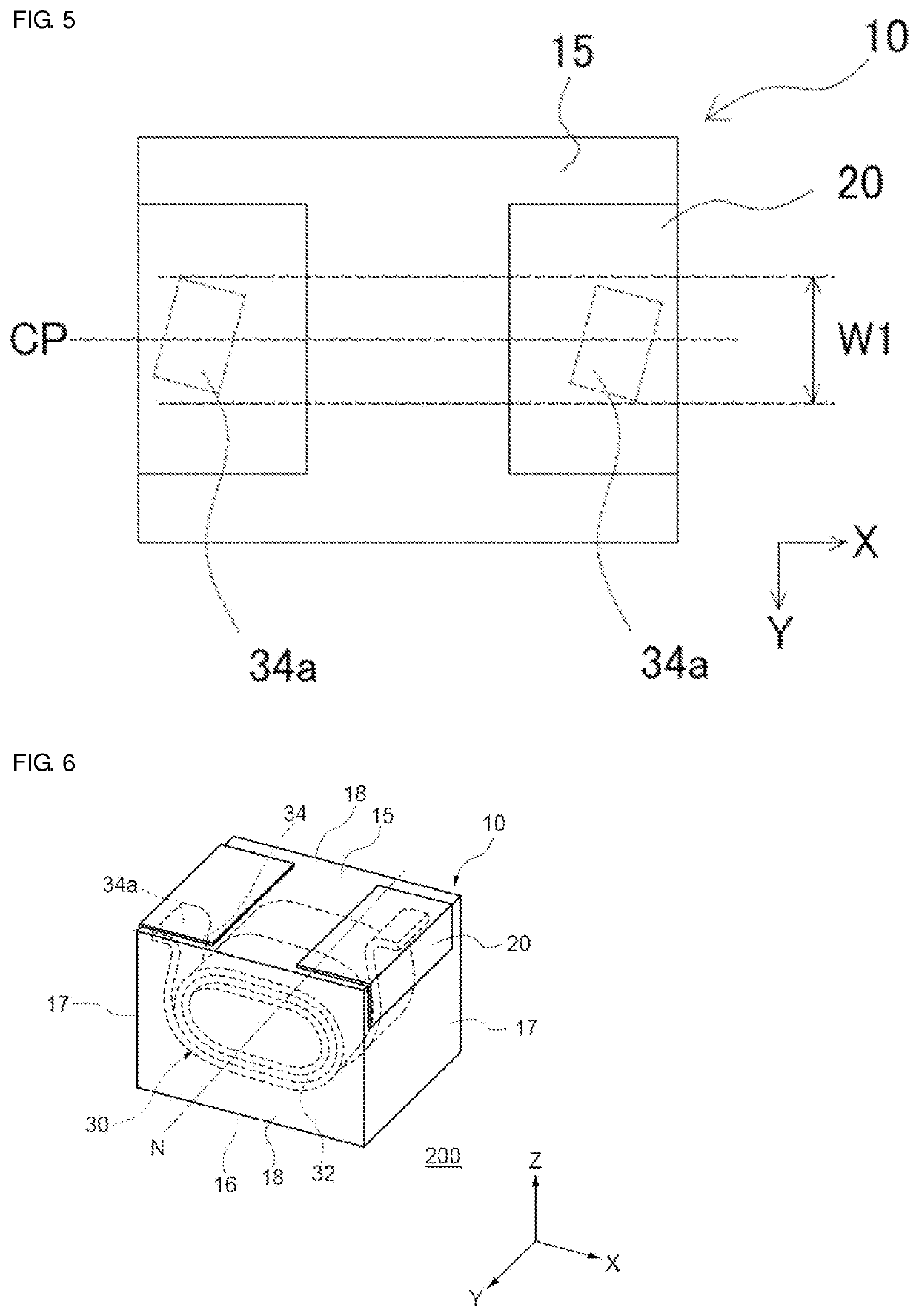
[0039]Reference Example 1 . FIG. 6 illustrates a partial transparent perspective view of the inductor 200 as viewed from a mounting surface side. FIG. 7 is a schematic cross-sectional view at a plane parallel to the mounting surface and passing through a midpoint between the mounting surface and an upper surface, and FIG. 8 is a partial transparent plan view as viewed from the mounting surface side. The inductor 200 is configured similarly to the inductor 100 except that the winding portion 32 is arranged in a manner such that the winding axis N of the coil 30 is substantially orthogonal to the side surface 18 which is the first pair of surfaces, and is substantially parallel to the mounting surface 15, the upper surface 16, and the end surface 17.
[0040]In the inductor 200, as illustrated in FIG. 6, the winding portion 32 is enclosed in the element body 10 in a manner such that the winding axis N i...
embodiment 2
[0044]An inductor 110 of Embodiment 2 will be described with reference to FIG. 10. FIG. 10 illustrates a partial transparent plan view as viewed from a mounting surface side of the inductor 110. The inductor 110 is configured in the same manner as the inductor 100 except that the shape of the exposed portion is different.
[0045]As illustrated in FIG. 10, in the inductor 110, an end surface of the conductor intersecting the length direction of the conductor (a cross section of the conductor orthogonal to a length direction of the conductor) at the end portion of the extended portion 34 is substantially parallel to the end surface 17 which is the second pair of surfaces. As such, the exposed portion 34b has a substantially trapezoidal shape defined by a length L21 of an upper bottom, a length L22 of a lower bottom, and a height W21. A height direction of the trapezoid, that is, a width direction of the conductor intersects the end surface 17, for example, at the angle θ. Further, the e...
embodiment 3
[0048]An inductor 120 of Embodiment 3 will now be described with reference to FIG. 13 to FIG. 15. FIG. 13 illustrates a partial transparent perspective view of the inductor 120 as viewed from a mounting surface side. FIG. 14 is a schematic cross-sectional view at a plane orthogonal to the mounting surface taken along a line A-A in FIG. 13. FIG. 15 is a schematic cross-sectional view at a plane orthogonal to the mounting surface taken along a line B-B in FIG. 13. The inductor 120 is configured in the same manner as the inductor 100 except that the winding portion is arranged while the winding axis N of the coil intersects the mounting surface and the upper surface, that the extended portions are respectively extended to the end surface side of the element body, and that the exposed portion is provided on the end surface of the element body.
[0049]In the inductor 120, the mounting surface 15 and the upper surface 16 of the element body 10 are formed as the first pair of surfaces, the e...
PUM
 Abstract
Description
Claims
Application Information