
Free-form surface micro-milling cutting force modeling method

A technology of micro-milling and modeling methods, which is applied in the fields of instruments, computing, and electrical digital data processing, etc., and can solve the problems of low model accuracy, inaccurate calculation of instantaneous cutting thickness, time-consuming and high cost

Active Publication Date: 2015-11-18
HUAZHONG UNIV OF SCI & TECH
View PDF3 Cites 38 Cited by
  • Summary
  • Abstract
  • Description
  • Claims
  • Application Information

AI Technical Summary

Problems solved by technology

Second, in the field of cutting force modeling for free-form surface micro-milling, only a few scholars have established mechanical force models and finite element models. It is necessary to calibrate the cutting force coefficients through a large number of cutting experiments or finite element simulations, which is time-consuming and expensive. And the model accuracy is not high
Third, the existing cutting force models rarely consider both tool eccentricity and tool deformation in the process of calculating the instantaneous cutting thickness, resulting in inaccurate calculation of the instantaneous cutting thickness

Method used


Image

  • Free-form surface micro-milling cutting force modeling method
  • Free-form surface micro-milling cutting force modeling method
  • Free-form surface micro-milling cutting force modeling method

Examples


Embodiment Construction

[0056] In order to make the objectives, technical solutions, and advantages of the present invention clearer, the following further describes the present invention in detail with reference to the accompanying drawings and embodiments. It should be understood that the specific embodiments described here are only used to explain the present invention, but not to limit the present invention. In addition, the technical features involved in the various embodiments of the present invention described below can be combined with each other as long as they do not conflict with each other.

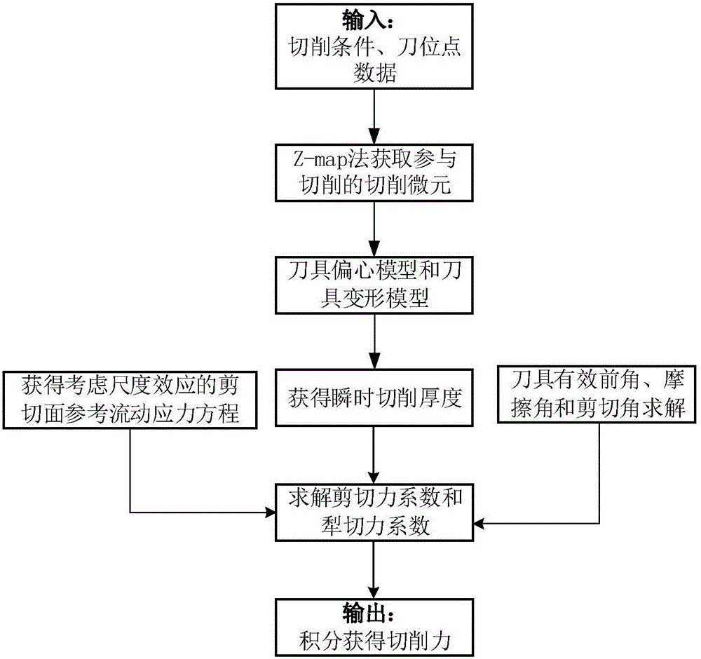
[0057] Such as figure 1 As shown, the free-form surface micro-milling cutting force modeling method of the embodiment of the present invention includes the following steps:

[0058] (1) Obtain processing parameters.

[0059] Determine the processing parameters according to the cutting conditions, surface quality and other requirements. Processing parameters include: micro-diameter ball nose tool tool rad...


PUM


Abstract

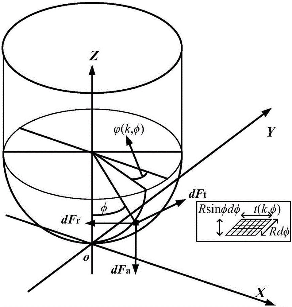
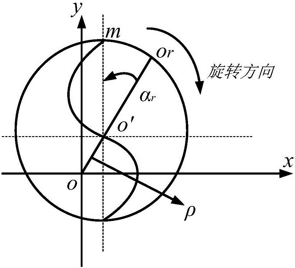
The invention discloses a free-form surface micro-milling cutting force modeling method. The free-form surface micro-milling cutting force modeling method comprises the following steps of (1) obtaining machining parameters including the radius R of a cutter, a helix angle beta of the cutter, the number Nf of cutting edges, the feed amount ft of each tooth, an eccentric distance p of the cutter and the initial eccentric angle alpha of the cutter, (2) dispersing the cutting edges of the cutter in the axial direction to form a series of cutting micro-elements and obtaining cutting micro-elements involved with cutting, (3) calculating the instantaneous cutting thickness of the cutting micro-element P (k, phi) with an axial angle phi of the current cutting edge, (4) calculating the cutting force of the micro-element P (k, phi) and (5) calculating the sum of the parameters obtained in the steps (3) and (4) and the cutting forces of the micro-elements involved with cutting to obtain the cutting force of the cutter. By means of the free-form surface micro-milling cutting force modeling method, the micro-milling cutting force of a free-form surface can be efficiently and accurately predicted.

Description

Technical field [0001] The invention belongs to the technical field of micro-milling processing, and more specifically, relates to a free-form surface micro-milling cutting force modeling method. Background technique [0002] Prediction of micro-milling force is the basis of micro-milling machining accuracy control, surface integrity and other related research, and it occupies an important position in related research in the field of micro-milling. At present, the research on the cutting force of conventional milling is relatively mature. Although the related research of micro-milling can be used for reference, there is still a big difference between the two. [0003] In the field of conventional milling, the tool and spindle can withstand large cutting forces, the feed per tooth is large (usually much larger than the cutting edge radius of the tool), and the milling force is almost all shearing force; while in micro milling , The cutting force of the tool and the spindle is relat...

Claims


Application Information

Patent Timeline
Patent Type & Authority Applications(China)
IPC IPC(8): G06F17/50
Inventor 彭芳瑜周林杨岑岑姚培锋占策刘明闫蓉李斌
Owner HUAZHONG UNIV OF SCI & TECH
Learn More