Low-current pneumatic knife switch

A technology of small current and knife switch, applied in the direction of electrical components, power devices inside the switch, etc., can solve the problems of inability to realize remote control, low degree of automation, long opening and closing time, etc., and achieve convenient use, high degree of automation, and structure simple effect

Inactive Publication Date: 2015-11-18
上科智能电气(苏州)有限公司
View PDF9 Cites 2 Cited by
  • Summary
  • Abstract
  • Description
  • Claims
  • Application Information

AI Technical Summary

Problems solved by technology

[0003] In the existing technology, the ordinary electric pneumatic knife switch used in the factory has a large size and a complicated structure. It requires a certain space to open and close, and the opening and closing time is long. Remote control cannot be realized, and the degree of automation is low.

Method used


Image

  • Low-current pneumatic knife switch

Examples


Embodiment Construction

[0013] The following will clearly and completely describe the technical solutions in the embodiments of the present invention. Obviously, the described embodiments are only some of the embodiments of the present invention, rather than all the embodiments. Based on the embodiments of the present invention, all other embodiments obtained by persons of ordinary skill in the art without making creative efforts belong to the protection scope of the present invention.

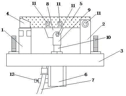
[0014] like figure 1 As shown, embodiments of the present invention include:

[0015] A small current pneumatic knife switch, comprising a first support 1, a second support 2, a base 3, a knife holder 4, a blade 5, an electric control box 6 and an air pipe 7, the first support 1 and the second support 2 are respectively Installed on the left and right ends of the top of the base 3, the knife holder 4 is installed on the upper port of the first bracket 1, the blade 5 is installed laterally between the second bracket ...


PUM


Abstract

The invention discloses a low-current pneumatic knife switch comprising a first bracket, a second bracket, a base, a knife holder, a knife blade, an electric control box, and an air pipe. The first bracket and the second bracket are respectively mounted at the left and right ends of the upper part of the base. The knife holder is mounted at an upper port of the first bracket. The knife blade is transversely mounted between the second bracket and the knife holder. The electric control box is mounted at the bottom of the base. The air pipe is mounted at the bottom of the base, and is disposed at one lateral side of the electric control box. Through the scheme, the low-current pneumatic knife switch provided by the invention is simple in structure and convenient to use. Under control of low current of the electric control box, an input air source signal is converted into required pressure to make the knife blade opened to a corresponding position. Knife blade positioning can be controlled accurately. The low-current pneumatic knife switch has a high degree of automation.

Description

technical field [0001] The invention relates to the field of electronic products, in particular to a low-current pneumatic knife switch. Background technique [0002] With the widespread use of domestic intelligent equipment, all kinds of products are constantly improving, deepening, and innovating. Various unfavorable factors in the application process of the product, the electro-pneumatic knife switch is a product that continues to deepen in this context. [0003] In the prior art, the common electropneumatic control knife switch used in the factory has a large size and a complex structure, requires a certain space to open, takes a long time to open and close, cannot realize remote control, and has a low degree of automation. Contents of the invention [0004] The technical problem mainly solved by the present invention is to provide a small current pneumatic knife switch, which is simple in structure and easy to use. To the corresponding position, the positioning of t...

Claims


Application Information

Patent Timeline
Patent Type & Authority Applications(China)
IPC IPC(8): H01H21/54H01H3/24
CPCH01H21/54H01H3/24
Inventor 许铭
Owner 上科智能电气(苏州)有限公司
Why Eureka
Try Eureka