
Eureka
For R&D, Eureka makes reading and utilizing patents & technical documents easy.
Eureka AIR
Designed for self-driven R&D workflows. Generate viable solutions, solve complex R&D challenges, empower your innovation with AI.

Eureka Materials
Designed for material experts only. Revolutionize your material R&D, from search, analyze, to developing new materials.

TechResearch
Generate reliable direction feasibility study reports for your R&D in just a few steps.

TechSeek
Discover and master advanced knowledge NOW. Basics, ideas, possibilities, all at once.

TechMind
As an expert in R&D Theories, TechMind can generates customized viable solutions instantly.

TechRisk
Analyze your overall solution with one click, know your potential R&D risks in advance.

TechMonitor
Get weekly tech updates, stay abreast of the latest tech innovations and key insights.
Ethernet switch system
A switch and Ethernet technology, applied in the field of Ethernet switch systems, can solve the problems of occupying network resources, paralysis of the whole network, inability to achieve redundancy, etc., and achieve the effect of increasing network bandwidth, saving costs, and realizing equipment redundancy.
- Summary
- Abstract
- Description
- Claims
- Application Information
AI Technical Summary
Problems solved by technology
Method used
Image

Examples
Embodiment Construction
[0009] The present invention will be further described below in conjunction with accompanying drawing:
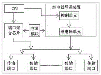
[0010] Such as figure 1 As shown, the Ethernet switch system of this embodiment includes a housing and a transmission interface located at the end of the housing. The housing is provided with a port aggregation chip, a power module and a relay conducting device, and the port aggregation chip is installed in the housing. The CPU of the switch is connected to the power module, which is used to realize the port aggregation of the switch after the switch is started. The power module is connected.
[0011] The relay conducting device includes a control unit and a relay protection unit. The control unit is connected to the CPU to receive the control signal from the CPU and control the relay unit to work according to the control signal. The contacts of the relay unit are connected in series to the input of the switch in pairs Between the output ports, and its contacts correspond...
PUM
 Abstract
Description
Claims
Application Information
 - R&D Engineer
- R&D Manager
- IP Professional
- Industry Leading Data Capabilities
- Powerful AI technology
- Patent DNA Extraction
Browse by: Latest US Patents, China's latest patents, Technical Efficacy Thesaurus, Application Domain, Technology Topic, Popular Technical Reports.
© 2024 PatSnap. All rights reserved.Legal|Privacy policy|Modern Slavery Act Transparency Statement|Sitemap|About US| Contact US: help@patsnap.com