Eureka AIR delivers breakthrough ideas for toughest innovation challenges, trusted by R&D personnel around the world.

Method for starting a combustion system

A technology of combustion system and fuel system, applied in combustion method, control combustion, engine starting, etc., can solve problems such as high loss coefficient, and achieve the effect of reliable operation

Inactive Publication Date: 2015-11-18
SIEMENS AG
View PDF5 Cites 0 Cited by
  • Summary
  • Abstract
  • Description
  • Claims
  • Application Information

AI Technical Summary

Problems solved by technology

However, due to the difference in loss coefficients of the hot and cold burners, already fired burner(s) have higher loss coefficients and thus less air will flow through the hot burner(s)

Method used


Image

  • Method for starting a combustion system
  • Method for starting a combustion system
  • Method for starting a combustion system

Examples


Embodiment Construction

[0045] The illustrations in the figures are schematic. It is to be noted that in different figures, similar or identical elements are provided with the same reference numerals.

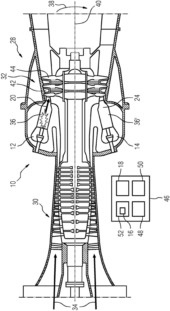
[0046] figure 1 A flow engine 28 , such as a gas turbine, is shown schematically. The flow motor 28 is included in a flow direction 34 of a flow medium, such as air (see figure 1 arrow pointing from the left-hand side to the right-hand side) a compressor 30 , a combustion system 10 and a turbine 32 arranged one behind the other. In the compressor 30 , the incoming fluid medium is compressed for use in one or more combustion chambers of the combustion system 10 . The combustion system 10 comprises in this exemplary embodiment several can-shaped combustion chambers 36, 36' separated by walls not shown and arranged one behind the other in the circumferential direction 38 around the axis 40 of the flow engine 28. In general, it is also possible to design a combustion system with a single annular ...


PUM


Abstract

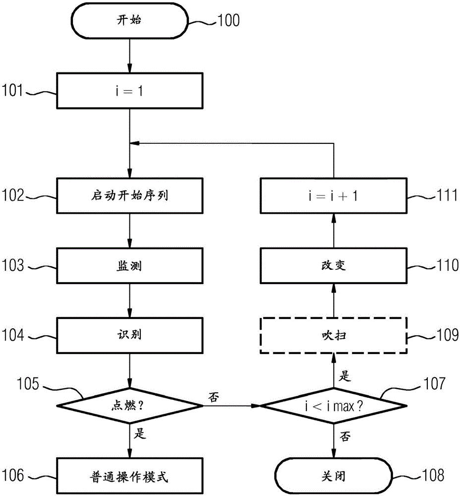
The present invention relates to a method for starting (100) a combustion system (10, 10a), comprising a first ignition device (12) and an at least second ignition device (14), a processing unit (16) and a sensor system (18). To obtain a reliable ignition the method comprises as a starting sequence at least the following steps: monitoring (103) during a working condition of the combustion system (10, 10a) an operational state of the first and the at least second ignition device (12, 14) by the sensor system (18); identifying (104) a predefined state of the first and / or the at least second ignition device (12, 14) by the processing unit (16); and as a further step: in case of an identification of the predefined state changing (110) in at least one parameter of at least one of the ignition devices (12, 14) by the processing unit (16). The invention further relates to a combustion system (10, 10a) equipped to be operable with said method as well as to a flow engine (28) with such a combustion system (10, 10a).

Description

technical field [0001] The present invention relates to a method for starting a combustion system, in particular a combustion system used in a flow engine, and to a combustion system equipped to be operable with said method and to a flow engine having such a combustion system. In particular, the present invention addresses the starting reliability of flow engines, such as gas turbine engines, particularly with regard to achieving ignition or ignition (ie, achieving flame sustain). Background technique [0002] Optimal firing conditions for gas turbine engines are subject to variation between starts due to various factors such as ambient temperature, gas turbine temperature, fuel heating value, fuel content, pressure, fuel and air delivery systems repeatability, etc. In a typical starting system for a gas turbine engine one uses an auxiliary drive unit for driving the gas turbine and a control unit that provides a start sequence in which the gas turbine speed and fuel delive...

Claims


Application Information

Patent Timeline
Patent Type & Authority Applications(China)
IPC IPC(8): F01D19/00F02C7/26
CPCF01D19/00F02C7/26F05D2260/85F23N2027/02F23N2041/20F23N2227/02F23N2241/20
Inventor K-K·拉姆
Owner SIEMENS AG
Why Eureka
Eureka Blog
Learn More