A fiber membrane dehydrator for dialyzer and dehydration process

A dialyzer and fiber membrane technology, which is applied in the field of dialyzer fiber membrane dehydration machine and dehydration process, can solve the problems that the dialyzer fiber membrane bundle is greatly affected, and achieve the effects of guaranteed quality and performance, increased production capacity, and simple structure

Active Publication Date: 2017-05-17
WUHAN HUACHENG CHUANGFU MEDICAL TECH
View PDF3 Cites 0 Cited by
  • Summary
  • Abstract
  • Description
  • Claims
  • Application Information

AI Technical Summary

Problems solved by technology

[0002] In the dialyzer production process, in order to detect whether a single fiber membrane of the dialyzer is damaged (a single fiber membrane bundle has about 10,000 membranes), it is necessary to inject a large amount of water into the fiber membrane bundles in the dialyzer, so that the fiber membrane bundles The inside of the dialyzer shell is fully wetted, and the pores of the fiber membrane wall are blocked by water molecules to prepare for the next step of testing; however, after the test is completed, the fiber membrane bundles of the dialyzer need to be dried to the set value. It is: water injection—detection—drying; because it is fully wet and the fiber membrane is a semipermeable membrane, after water injection and detection, about 50 grams of water remains in the fiber membrane bundle of the dialyzer, and the subsequent drying equipment needs to remove about 50 grams of water. The fiber membrane bundles are all dried to the set value. The drying time of the existing single dialyzer fiber membrane bundles is about 18 minutes. The long-term high temperature during drying has a considerable impact on the performance of the dialyzer fiber membrane bundles.

Method used


Image

  • A fiber membrane dehydrator for dialyzer and dehydration process
  • A fiber membrane dehydrator for dialyzer and dehydration process
  • A fiber membrane dehydrator for dialyzer and dehydration process

Examples


Embodiment Construction

[0014] In order to make the object, technical solution and advantages of the present invention clearer, the present invention will be further described in detail below in conjunction with the accompanying drawings and embodiments. It should be understood that the specific embodiments described here are only used to explain the present invention, not to limit the present invention.

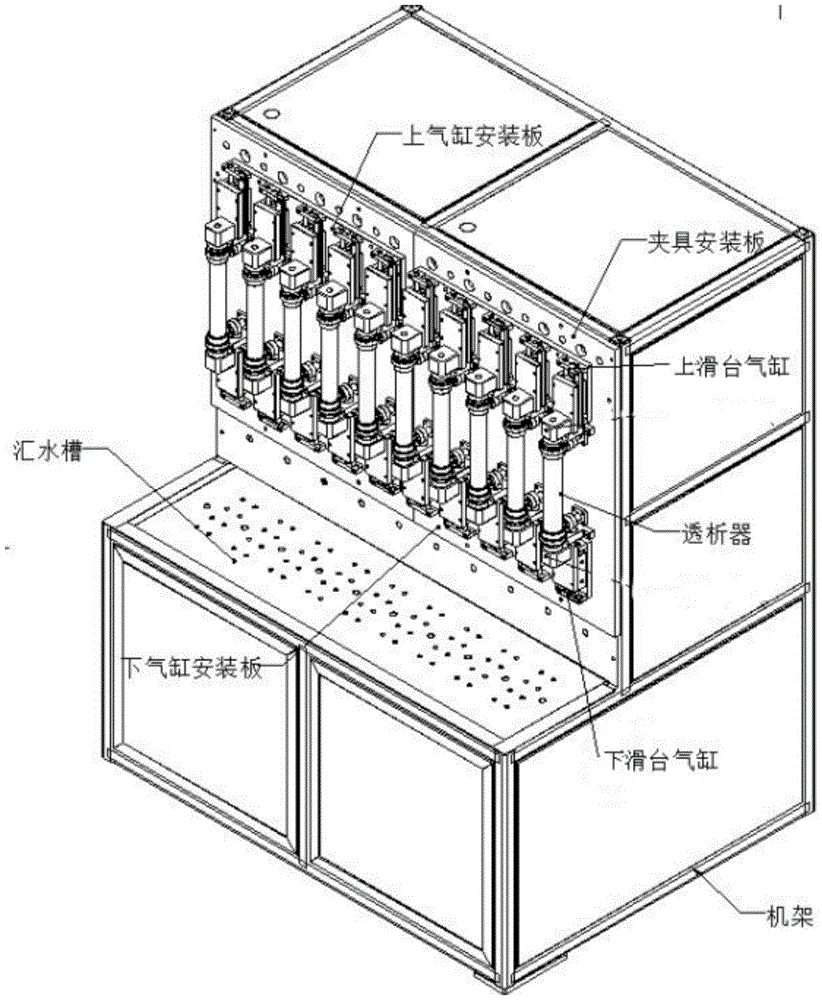
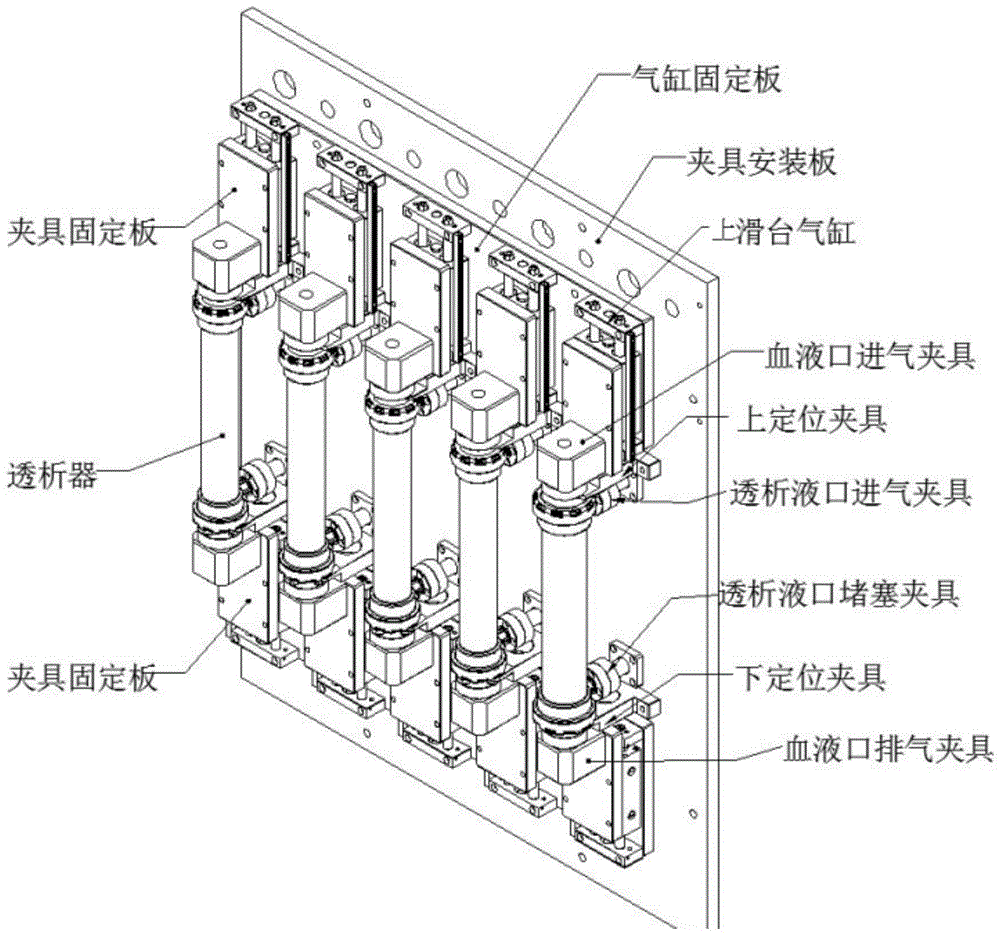
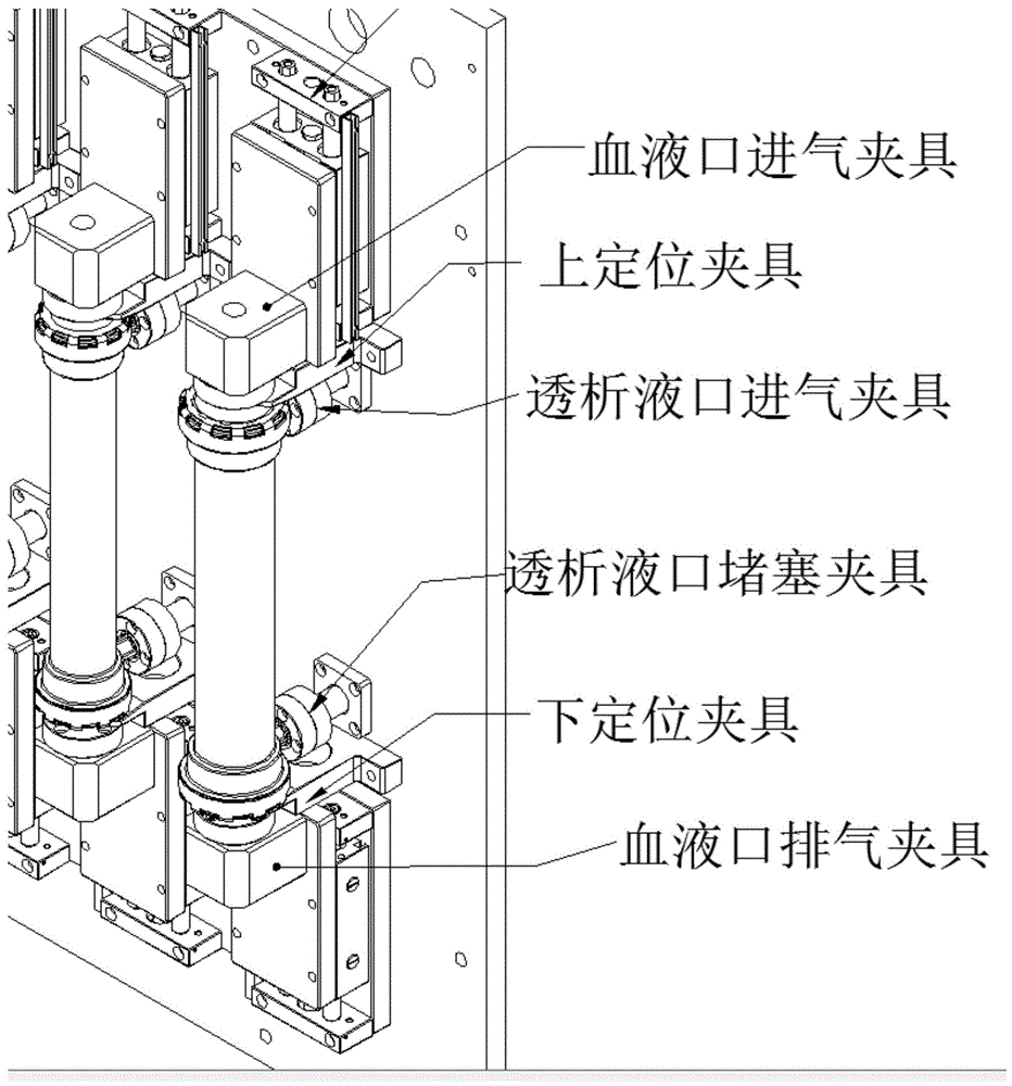
[0015] In an embodiment of the present invention, a fibrous membrane dehydrator for a dialyzer is provided, which includes a frame, a fixture mounting plate, a sump, an upper cylinder mounting plate, a lower cylinder mounting plate, an upper slide cylinder, a lower slide cylinder, and a blood inlet inlet Fixtures, blood port exhaust fixtures, upper positioning fixtures, lower positioning fixtures, dialysate inlet fixtures, dialysate port blockage fixtures; the fixture mounting plate is fixed on the upper part of the frame, the sink is fixed on the lower part of the frame, and the upper The sliding ...


PUM


Abstract

The present invention discloses a fiber membrane dehydrator for dialyzer and a dehydration process. The fiber membrane dehydrator for dialyzer includes a jig mounting plate fixed to the upper part of a rack, a water catchment sink fixed to the lower of the rack, an upper slider cylinder fixed to the upper part of the jig mounting plate by an upper cylinder mounting plate, a lower slider cylinder fixed to the lower part of the jig mounting plate by a lower cylinder mounting plate, a blood port air inlet clamp fixedly connected on the upper slider cylinder, and a blood port exhaust clamp fixedly connected with the lower slider cylinder. An upper positioning clamp and a lower positioning clamp are used for fixing the dialyzer; a dialysate port air intake clamp is fixed on the upper positioning clamp; and a dialysate port plug clamp is fixed to the lower positioning clamp. The fiber membrane dehydrator for dialyzer is simple in structure and easy for process operation, improves the production capacity of a single dehydrator, greatly reduces damage on dialyzer fiber membrane bundle membrane due to reduced high-temperature drying time, and ensures the quality and performance of the dialyzer fiber membrane.

Description

technical field [0001] The invention belongs to the field of dialyzer production, and in particular relates to a fiber membrane dehydrator for a dialyzer and a dehydration process. Background technique [0002] In the dialyzer production process, in order to detect whether a single fiber membrane of the dialyzer is damaged (a single fiber membrane bundle has about 10,000 membranes), it is necessary to inject a large amount of water into the fiber membrane bundles in the dialyzer, so that the fiber membrane bundles The inside of the dialyzer shell is fully wetted, and the pores of the fiber membrane wall are blocked by water molecules to prepare for the next step of testing; however, after the test is completed, the fiber membrane bundles of the dialyzer need to be dried to the set value. It is: water injection—detection—drying; because it is fully wet and the fiber membrane is a semipermeable membrane, after water injection and detection, about 50 grams of water remains in t...

Claims


Application Information

Patent Timeline
Patent Type & Authority Patents(China)
IPC IPC(8): B01D67/00B01D69/08
Inventor 贺磊贺年
Owner WUHAN HUACHENG CHUANGFU MEDICAL TECH
Why Eureka
Try Eureka