Coal pulverizer equipment

A coal pulverizer and coal pulverizing technology, applied in the field of coal pulverizer devices, can solve problems such as boiler efficiency reduction and the like

Inactive Publication Date: 2015-11-25
XUZHOU QUANZHONG ELECTRIC POWER TECH CO LTD
View PDF9 Cites 4 Cited by
  • Summary
  • Abstract
  • Description
  • Claims
  • Application Information

AI Technical Summary

Problems solved by technology

According to the national regulations DL / T5145-2002 "Technical Regulations for Design and Calculation of Coal Milling System in Thermal Power Plants", for the direct-blown pulverization system, when V daf M2 =[(82-V daf )5 / 3±5], V daf >40%, T M2 M2 After being limited to this range, a large amount of cold air must be mixed into the coal mill, resulting in a reduction in boiler efficiency

Method used


Image

  • Coal pulverizer equipment
  • Coal pulverizer equipment
  • Coal pulverizer equipment

Examples


Embodiment Construction

[0021] The following will clearly and completely describe the technical solutions in the embodiments of the present invention with reference to the drawings in the embodiments of the present invention.

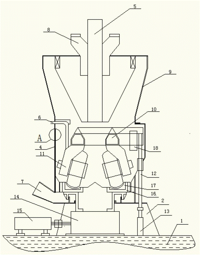
[0022] The present invention provides a coal mill device, the working principle of which is to greatly reduce the residence time of pulverized coal in the coal mill by changing the internal mechanism of the pulverizing system, improve the safety performance of the pulverizing system, and further increase the outlet heat of the coal mill once. The air temperature increases the proportion of hot air entering and reduces the proportion of cold air entering to achieve the purpose of increasing the outlet temperature of the coal mill, reducing the carbon content of boiler fly ash, reducing the carbon content of slag and improving boiler efficiency.

[0023] The present invention will be described in further detail below in conjunction with examples and specific implementation method...


PUM


Abstract

The invention discloses coal pulverizer equipment. The coal pulverizer equipment comprises a base, wherein a body support is arranged on the base, a sealed barrel with smooth and flat inner walls is connected onto the body support, all inner walls of the barrel are in smooth transition, a plurality of barrel liner plates are arranged on the inner walls of the barrel, and a mounting gap between the adjacent barrel liner plates is sealed by an inorganic material; a coal feeding pipe is arranged in the center of the top of the barrel, and a grinding roller assembly is arranged below the coal feeding pipe; a sealing air pipe is connected onto the grinding roller assembly, an air inlet is formed in the bottom of the barrel, and a pulverized coal discharge pipe is arranged at the top of the barrel and is connected with a vertically mounted separator. A local mechanism in a coal pulverizing system is changed, so that the retaining time of pulverized coal in the coal pulverizer is shortened, the safety performance of the coal pulverizing system is improved, then the temperature of hot primary air at an outlet of the coal pulverizer is increased, the hot air entering proportion is increased, the cold air entering proportion is decreased, and the purposes of reduction of carbon content of slag and improvement of boiler efficiency are achieved while the temperature of the outlet of the coal pulverizer is increased and the carbon content of fly ash of a boiler is reduced.

Description

technical field [0001] The invention relates to the field of coal combustion, in particular to a coal pulverizer device. Background technique [0002] In coal-fired power plant boilers, in order to improve the combustion rate and ignition performance of pulverized coal, coal pulverizers are widely used to grind raw coal into pulverized coal and send it into the furnace for combustion through pipelines. In the process of sending the raw coal into the furnace after being ground by the coal mill, there are two ways: 1. The direct blowing pulverizing system, that is, the coal is directly sent to the furnace for combustion through the pipeline after being ground by the coal mill; 2. The silo-type pulverizing system, that is, the coal is ground by the coal mill and sent to the silo through the pipeline, and then enters the pipeline through the pulverizer at the lower part of the silo and then sent to the furnace for combustion. According to the national regulations DL / T5145-2002 ...

Claims


Application Information

Patent Timeline
Patent Type & Authority Applications(China)
IPC IPC(8): B02C4/02B02C4/28
Inventor 张云
Owner XUZHOU QUANZHONG ELECTRIC POWER TECH CO LTD
Why Eureka
Try Eureka