Through hole forging forming method

A step-shaped and punch technology is applied in the field of forging and forming of through holes, which can solve the problems of material waste and prolong processing cycle, and achieve the effects of preventing shrinkage, saving materials and time, and achieving good economic benefits.

Active Publication Date: 2015-11-25
SHAANXI HONGYUAN AVIATION FORGING
View PDF6 Cites 4 Cited by
  • Summary
  • Abstract
  • Description
  • Claims
  • Application Information

AI Technical Summary

Problems solved by technology

The invention discloses a special method for one-time forging and forming through-holes for relatively high blanks. By designing a special superimposed small straight punch, the

Method used


Image

  • Through hole forging forming method
  • Through hole forging forming method
  • Through hole forging forming method

Examples


Embodiment Construction

[0023] The present invention will be described in further detail below in conjunction with accompanying drawing by specific embodiment:

[0024] A billet: size φ450×570, material 30Si2MnCrMoVE, required central through hole size ×570. The specific processing steps are as follows:

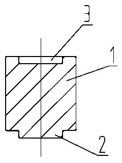
[0025] The first step is to make 8 special small punches of φ110×120. The shape of the small punches is as follows figure 1 As shown, it includes a body 1 , a positioning boss 2 and a positioning concave platform 3 .

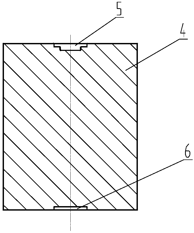
[0026] The second step, such as figure 2 As shown, the blank 4 is pre-processed, and the step-shaped positioning concave platform on the upper surface and the positioning concave platform on the lower surface are processed.

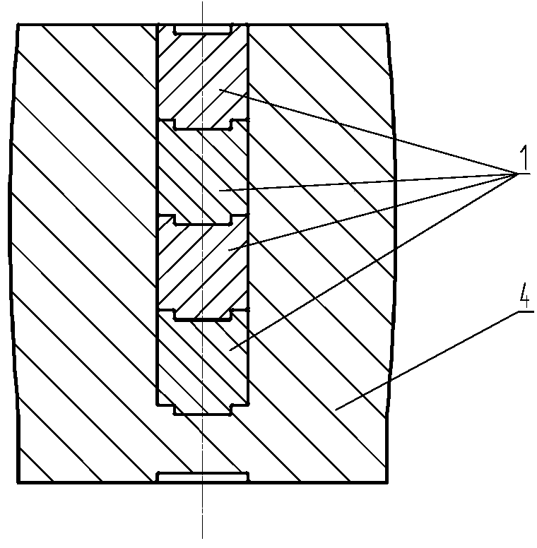
[0027] The third step is to preheat all 8 small punches. After the blank is heated out of the furnace, the step-shaped positioning concave platform is facing upwards. The positioning convex platform of the first punch is aligned with the step-shaped positio...


PUM


Abstract

The invention relates to a through hole forging forming method. For a blank with the height being greater than 350mm, the forging processing forming of a through hole is very difficult. The invention discloses a special method for forging and forming a through hole in one step in a higher blank. A special laminated small-size straight punching head is designed, so that a cake blank can be heated in one step to forge the through hole; and the problems of material waste and extended processing period due to mechanical processing are avoided.

Description

technical field [0001] The invention belongs to the technical field of forging, and relates to a forging forming method of a through hole. Background technique [0002] With the continuous advancement of science and technology, the requirements for equipment capabilities continue to increase, causing structural changes in some ring forgings, such as: the high cylinder originally welded by 2 or 3 ring forgings is now designed as a whole high cylinder Forgings; various equipment needs to increase power, forcing the height of the ring forgings in the engine to be higher than before, etc. These all need to process the through hole first from the taller blank, and then forge it into a high tube forging. For blanks with a height greater than 350 mm, it is very difficult to forge the through holes. Usually, the following methods are used: (1) first heat the cake blank to punch out the blind holes, and then machine them into through holes. (2) Directly use a larger-sized cake base...

Claims


Application Information

Patent Timeline
IPC IPC(8): B21J5/10B21J13/02
CPCB21J5/10
Inventor 牛晓恒冀胜利李增乐惠斌
Owner SHAANXI HONGYUAN AVIATION FORGING
Why Eureka
Try Eureka