Shaping equipment for bus duct insulation film

A technology of insulating film and busway, which is applied in metal processing and other directions, can solve the problems of waste of manpower and material resources, low shearing efficiency, size setting, temperature control and feeding speed, etc., to achieve high forming efficiency, improve cutting efficiency, Good hemming effect

Active Publication Date: 2015-11-25
NINGBO GELAITE ELECTRICITY VAPOR CREATES
View PDF7 Cites 6 Cited by
  • Summary
  • Abstract
  • Description
  • Claims
  • Application Information

AI Technical Summary

Problems solved by technology

It brings great convenience for power feeding, installation and maintenance. The insulating film of busway is one of the most important auxiliary materials for dense busway. It has strict requirements on processing technology, mainly including dimensioning, temperature control, and feeding speed. It is difficult to control and will directly affect the product quality of the busway. The existing busway insulation film setting machine on the market is formed by drawing materials, and the width of the insulation film is controlled by the baffles on both sides of the insulation film so that the cross section of the insulation film is "U". "type, but because the groove width of the formed insulating film generally changes with the width of the bus duct, when the bus duct insulating film shaping machine on the market is used, the folding effect of the insulating film is not good, and the insulating film is in the After the hemming is formed, the length of the insulating film is manually detected on the market, and then cut by hand. The cutting efficiency is low and a lot of manpower and material resources are wasted.

Method used


Image

  • Shaping equipment for bus duct insulation film
  • Shaping equipment for bus duct insulation film
  • Shaping equipment for bus duct insulation film

Examples


Embodiment Construction

[0025] In order to have a further understanding and understanding of the structural features of the present invention and the achieved effects, the preferred embodiments and accompanying drawings will be used for a detailed description, as follows:

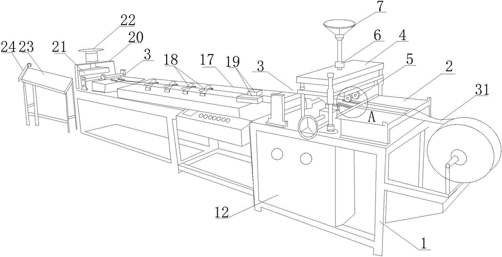
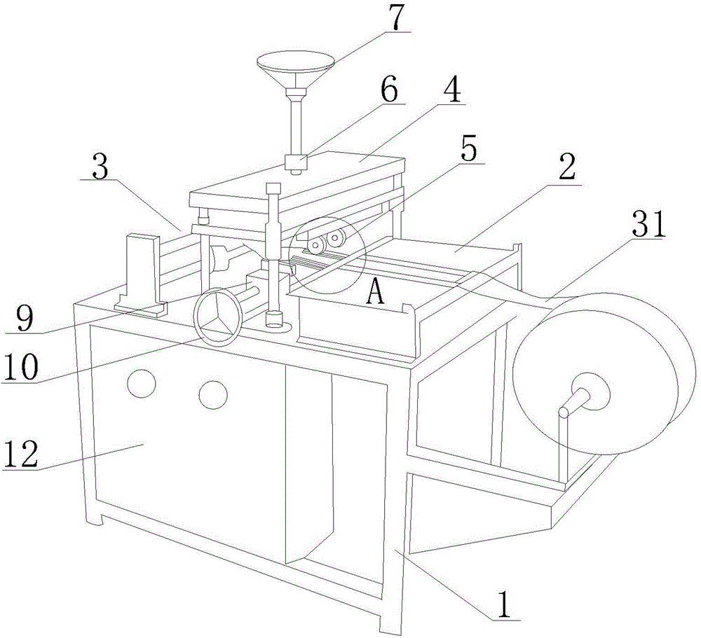
[0026] Such as Figure 1 to Figure 3 As shown, a busway insulation film shaping equipment includes a bracket 1, a feeding table 2 arranged on the bracket 1, a material pulling device located on one side of the feeding table 2, and a feeding mechanism 3 located on both sides of the material pulling device. The platform 2 is equipped with an insulating film positioning preheating structure, and the side of the pulling device away from the feeding platform 2 is equipped with an automatic material cutting device.

[0027] The insulating film positioning and preheating structure includes a positioning structure and a preheating structure, wherein the positioning structure includes a lifting platform 4 arranged between the feeding platf...


PUM


Abstract

The invention relates to shaping equipment for a bus duct insulation film. The shaping equipment comprises a bracket, a feeding table, a material pulling device and a feeding mechanism, wherein the feeding table is arranged on the bracket; the material pulling device is arranged on one side of the feeding table; the feeding mechanism is arranged on two sides of the material pulling device; an insulation film positioning preheating structure is arranged on the feeding table; an automatic cutting device is arranged on the side far away from the feeding table of the material pulling device. The positioning preheating device of the shaping equipment conducts positioning on the position of a to-be-folded edge of the insulation film through positioning wheels of the positioning mechanism; the positioning wheels are in tight contact with a preheating plate of the preheating structure to enable the position of the to-be-folded edge of the insulation film to be partially heated on the preheating plate; during the further material pulling forming procedure, the folding effect of the insulation film is good; width of a groove of the insulation film can be adjusted freely by adjusting the width between the two positioning wheels and the preheating plate; forming efficiency of the bus duct insulation film is high; the automatic cutting device realizes integration of loading, forming and cutting; under the condition that high forming efficiency is ensured, cutting efficiency is improved.

Description

technical field [0001] The invention relates to a sizing device, in particular to a sizing device for an insulating film of a bus duct. Background technique [0002] The bus bar refers to the connection of voltage distribution devices at all levels in the substation, as well as the connection of electrical equipment such as transformers and corresponding power distribution devices. Most of them use bare or stranded wires with rectangular or circular cross-sections, which are collectively called bus bars. The function of the busbar is to collect, distribute and transmit electric energy. With the emergence of modern engineering facilities and equipment, the power consumption of all walks of life has increased rapidly, especially the emergence of many high-rise buildings and large workshops. Traditional cables used as transmission wires It can no longer meet the requirements in the large current transmission system, and the parallel use of multiple cables has brought a lot of i...

Claims


Application Information

Patent Timeline
Patent Type & Authority Applications(China)
IPC IPC(8): B29C53/04B29C53/84B29C53/80B26D1/04B26D7/00B26D7/28B26D5/12
Inventor 黄宏斌毛友水
Owner NINGBO GELAITE ELECTRICITY VAPOR CREATES
Why Eureka
Try Eureka