Board machining push mechanism

A technology of pushing mechanism and plank, which is applied in the direction of conveyor objects, transportation and packaging, etc., can solve the problems of laboriousness, heavy weight, and reducing the processing efficiency and quality of planks, and achieve the effect of improving processing efficiency and quality, and simple structure

Inactive Publication Date: 2015-11-25
徐阳
View PDF6 Cites 9 Cited by
  • Summary
  • Abstract
  • Description
  • Claims
  • Application Information

AI Technical Summary

Problems solved by technology

[0002] At present, due to its convenient processing and certain strength, wood is widely used in our production and life, and is closely related to each of us. Wood is used by us to build houses, decorate indoor environments, and make indoor furniture. In the process, especially the processing of wood boards, the wood boards need to be processed according to the needs. During the processing of the wood boards, the wood boards need to be pushed horizontally, so that the wood boards can be processed sequentially and efficiently along the pushing direction of the wood boards. The traditional wood board push The process is generally pushed manually. Due to the large size and heavy weight of the wood, the workers are more laborious when pushing the wood, which increases the labor intensity of the workers. Moreover, due to the randomness of the wood pushing by the workers, it is difficult to accurately carry out according to the needs of wood processing. Pushing, the existing plank pushing mechanism is difficult to accurately limit the plank when pushing the plank, making the plank shake from side to side when pushing, reducing the efficiency and quality of plank processing, and cannot meet the needs of production and use

Method used


Image

  • Board machining push mechanism
  • Board machining push mechanism

Examples


Embodiment Construction

[0012] In order to further describe the present invention, a specific implementation of a wood processing and pushing mechanism will be further described below in conjunction with the accompanying drawings. The following examples are explanations of the present invention and the present invention is not limited to the following examples.

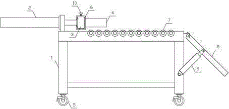
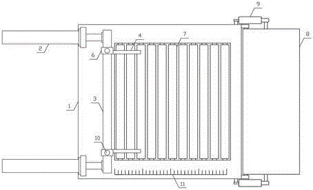
[0013] Such as figure 1 , figure 2 As shown, a wooden board processing push mechanism of the present invention includes a main support 1, a translation hydraulic cylinder 2, a push plate 3 and a limit plate 4, and a plurality of universal wheels 5 with brakes are uniformly arranged on the lower side of the main support 1, and the translation hydraulic pressure There are two cylinders 2, and the two translational hydraulic cylinders 2 are respectively arranged horizontally on both sides of one end of the main support 1, and the push plate 3 is horizontally arranged on the output ends of the two translational hydraulic cylinders 2, and the tw...


PUM


Abstract

The invention discloses a board machining push mechanism, and belongs to the field of wood machining mechanical equipment. The board machining push mechanism comprises a main bracket, translation hydraulic cylinders, a push plate and a limiting plate, wherein multiple brake universal wheels are uniformly arranged at the lower side of the main bracket; two translation hydraulic cylinders are horizontally arranged at the two sides of one end of the main bracket; the push plate is horizontally arranged at output ends of the two translation hydraulic cylinders; limiting sleeves are respectively arranged at the two sides of the push plate; the limiting plate is horizontally arranged at one sides of the limiting sleeves; the upper side of the main bracket is horizontally and rotationally connected with multiple wood guide rollers; the upper end of a wood guide bracket is hinged to the main bracket; wood guide hydraulic cylinders are respectively arranged between the two sides of the wood guide bracket and the main bracket; the tail ends of the wood guide hydraulic cylinders are hinged with the main bracket; and the output ends of the wood guide hydraulic cylinders are hinged to the middle part of the wood guide bracket. The board machining push mechanism is simple in structure, can quickly and efficiently move boards horizontally and accurately, improves the board machining efficiency and quality, and satisfies the production and use demands.

Description

technical field [0001] The invention belongs to the field of wood processing machinery and equipment, in particular to a wood processing push mechanism. Background technique [0002] At present, due to its convenient processing and certain strength, wood is widely used in our production and life, and is closely related to each of us. Wood is used by us to build houses, decorate indoor environments, and make indoor furniture. In the process, especially the processing of wood boards, the wood boards need to be processed according to the needs. During the processing of the wood boards, the wood boards need to be pushed horizontally, so that the wood boards can be processed sequentially and efficiently along the pushing direction of the wood boards. The traditional wood board push The process is generally pushed manually. Due to the large size and heavy weight of the wood, the workers are more laborious when pushing the wood, which increases the labor intensity of the workers. M...

Claims


Application Information

Patent Timeline
Patent Type & Authority Applications(China)
IPC IPC(8): B65G47/82
Inventor 徐阳
Owner 徐阳
Why Eureka
Try Eureka