
Application method of robot in surface treatment production

A surface treatment and application method technology, applied in the direction of manipulator, anodic oxidation, electrolysis process, etc., can solve the problems of many auxiliary mechanisms, insufficient manpower, slow running speed, etc., and achieve fast response speed, diversified actions, and shortened cycle Effect

Inactive Publication Date: 2015-11-25
KUNSHAN CITY XINDIANDING MECHANICAL EQUIP CO LTD
View PDF4 Cites 9 Cited by
  • Summary
  • Abstract
  • Description
  • Claims
  • Application Information

AI Technical Summary

Problems solved by technology

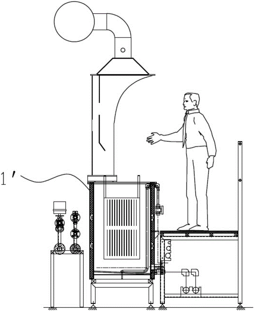
[0003] Manual processing equipment needs to complete various actions manually, and there are hidden dangers of physical injury caused by workers who are prone to fatigue and harsh environments. At the same time, the randomness of manual operation cannot guarantee the quality of products. No, there are inherent limitations
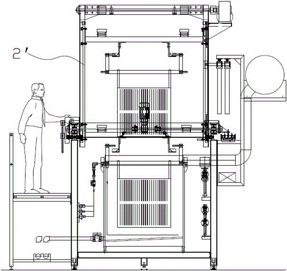
[0004] The crane 2' in traditional automatic electroplating equipment can only achieve single or fixed actions (traditional electroplating equipment cranes only have lifting and lateral movements). If functions such as tilting, rotating, and swinging are required, auxiliary mechanisms need to be added, and the structure is complex , in order to realize the process action, a complicated auxiliary mechanism is installed, which is mainly composed of a lifting motor, a traverse motor, a clamping cylinder device, a rotating motor device, and a tilting motor device. There are the following disadvantages in the actual use process:
[0005] 1. The adjustment range of the inclination angle is small, which cannot be adapted to various products. During the production process, small workpieces can be rotated. When changing long workpieces or relatively flat workpieces, the workpieces do not rotate during the rotation of the passivation basket, resulting in uneven passivation film thickness. Uniformity, which eventually leads to product scrap;
[0006] 2. The range of rotation speed adjustment is small. The speed reducer of the rotating motor reducer of the traditional rotating passivation crane is a fixed value. After selection, the speed can only be adjusted through the frequency converter, which cannot meet the process requirements of various products. a great limit;
[0007] 3. Due to the many auxiliary mechanisms of the traditional rotary passivation crane, all of which are composed of non-standard parts and many positioning devices, signal interference frequently occurs in the actual production process, resulting in malfunctions and equipment failures
[0008] 4. Occupies too much space, resulting in waste of space and energy
The structure of the traditional rotary passivation crane is complex
[0009] 5. Moreover, in the traditional electroplating equipment, the lifting and traversing speed of the crane is relatively slow, reaching 0.8m / s is the limit, and then there will be problems of inaccurate positioning or over-limit alarms that will affect production. Therefore, there are widespread operating Defects of slow speed and long running cycle
[0010] Furthermore, when it is necessary to adjust the angle or speed of the auxiliary mechanism of the traditional gantry crane, the small-scale adjustment can be set by the frequency converter, and the large-scale adjustment needs to be realized by replacing the reducer or the eccentricity of the eccentric wheel. In the actual production process, often due to The limitation of space location, it cannot be realized in the case of major renovation or modification

Method used


Image

  • Application method of robot in surface treatment production
  • Application method of robot in surface treatment production
  • Application method of robot in surface treatment production

Examples


Embodiment Construction

[0034] The technical solution in the embodiment will be specifically, clearly and completely described below in conjunction with the drawings in the embodiment.

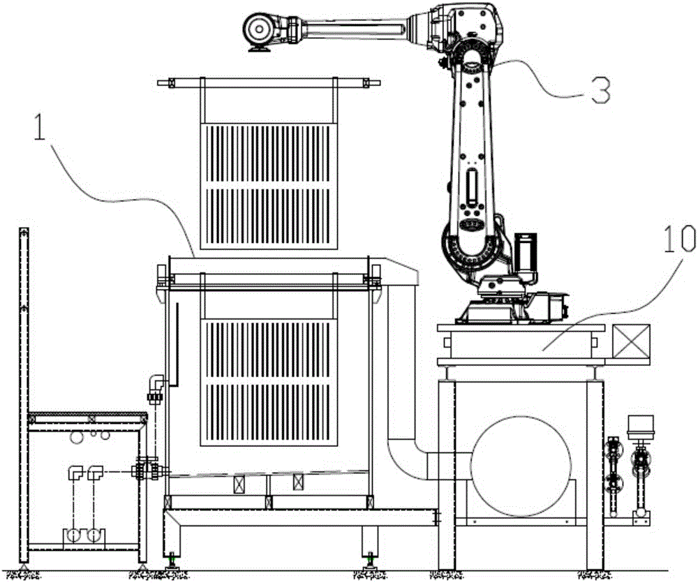
[0035] see image 3 Shown is a schematic diagram of the application state of the robot of the present invention in surface treatment production. The method comprises the steps of:

[0036] A movable robot 3 and its control system are provided. The robot 3 is placed on the robot track 10 of the surface treatment equipment 1. Through the control system, the robot 3 is controlled to perform various actions of the plated parts in each process. Specifically, the actions to be performed by the robot include lifting, walking, tilting, rotating, swinging and automatic opening and closing of the drum cover.

[0037] The invention uses robots to replace workers in manual equipment for handling, can complete various manual actions, solves the problem of worker fatigue and the physical injury caused by harsh environments to wo...


PUM


Abstract

The invention discloses an application method of a robot in surface treatment production. The method is particularly suitable for the electroplating process and treatment performed before and after electroplating and includes the following steps that the movable robot and a control system of the robot are arranged, the robot is arranged on a robot track of a surface treatment device, and the control system controls the robot to execute actions of a workpiece in all processes. The actions needing to be executed by the robot comprise that the robot drives the workpiece or a hanging tool to ascend, descend, move transversely, incline, rotate and swing and drives a cover of a rolling drum to be automatically opened and closed. The movable robot is adopted for replacing manpower transport in a manual treatment device or a crane and a transfer mechanism in a traditional automatic electroplating device to execute all the actions in all the processes; the actions include ascent, descent, walk, inclination, rotation, swing and automatic cover opening and closing of the rolling drum and are diverse in all directions without a dead angle; and the response moving speed is high, localization is accurate, a period is short, efficiency is improved, energy is saved, emission is reduced, intelligence is achieved, and control is more convenient.

Description

technical field [0001] The invention relates to an application method of a movable robot in surface treatment production, and belongs to the technical field of industrial electroplating and pre- and post-electroplating treatments. Background technique [0002] At present, in the field of industrial electroplating, such as figure 1 and figure 2 As shown, the processing process generally adopts human handling in manual processing equipment 1' or crane handling in traditional automatic processing equipment to perform various actions of the workpiece in each process, such as lifting, walking, tilting, rotating, swinging, and rolling. Functions such as automatic opening and closing of the cover. [0003] Manual processing equipment needs to complete various actions manually, and there are hidden dangers of physical injury caused by workers who are prone to fatigue and harsh environments. At the same time, the randomness of manual operation cannot guarantee the quality of produ...

Claims


Application Information

Patent Timeline
Patent Type & Authority Applications(China)
IPC IPC(8): C25D11/02C23F3/00C25D17/16C23C22/00B25J5/02
Inventor 俞光明
Owner KUNSHAN CITY XINDIANDING MECHANICAL EQUIP CO LTD
Learn More