A high-speed plastic circular weaving machine

A circular loom and plastic technology, applied in circular looms, looms, textiles, etc., can solve the problems of easy degumming, low operating speed, and low temperature resistance, and achieve low temperature rise, stable operation, and increased production speed. Effect

Active Publication Date: 2015-11-25
PINGYANG DAYU PLASTIC MACHINERY
View PDF9 Cites 13 Cited by
  • Summary
  • Abstract
  • Description
  • Claims
  • Application Information

AI Technical Summary

Problems solved by technology

[0005] 3. Steel rollers are used, the replacement cost of the rollers is high, the high-speed operation is easy to generate heat, the miniature bearings are easy to be damaged, and it is inconvenient to disassemble. Steps, when the warp yarn passes by, the shuttle wheel bends the warp yarn at 90 degrees and causes damage. The shuttle body is covered with a silicone plate and rolled by rollers. The silicone plate has a high damage rate under the rolling of the ro

Method used


Image

  • A high-speed plastic circular weaving machine
  • A high-speed plastic circular weaving machine
  • A high-speed plastic circular weaving machine

Examples


Embodiment 1

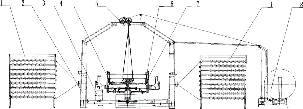
[0029] Example 1: as figure 1 As shown, a high-speed plastic circular loom includes an outer support (2), front and rear warp support (1), a lifting device (5), a cloth rolling device (8), a main engine transmission device (3), a weaving and opening device ( 4), the whole shuttle device (16), the door ring (6), the rolling track device (7). The outer bracket is arranged outside the main machine, the front and rear warp wire brackets are respectively arranged at the front and rear of the outer bracket, the lifting device is arranged on the top of the main machine and supported by the outer bracket, and the cloth winding device is arranged in the front part of the rear warp wire bracket.

Embodiment 2

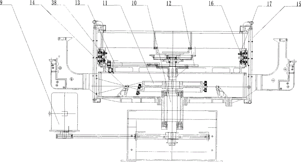
[0030] Example 2: as figure 2 As shown in the figure, the shuttle body is in the shape of a boat, and the rear part is provided with a rear roller (19). In addition, the whole shuttle is subjected to the centrifugal force outward during the movement, and there is a certain distance between the positioning wheel and the warp, so the woven product will not be damaged. Two or more conical positioning shuttle wheels (17) are installed on the inner side of the shuttle body, respectively. The positioning shuttle wheel is characterized by a wheel shaft (39) in the middle, and a concentric or eccentric mounting hole (40) in the wheel shaft. The axle is provided with more than one bearing (41), the outer bearing is provided with a steel sleeve (42), the outer steel sleeve is cast with a colloidal molding (43), and its conical angle is in rolling contact with the inclined plane steps on the inner plane of the upper and lower door rings. Because the upper and lower tapered rollers and ...

Embodiment 3

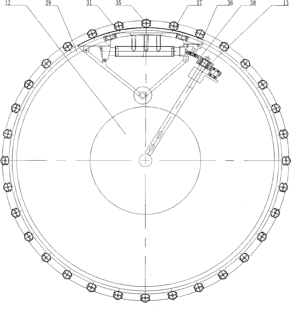
[0031] Example 3: as image 3 As shown, on the inner plane of the upper and lower door rings, there are inclined plane steps (29) that conform to the opening angle of the warp threads, and on the outer plane of the upper and lower door rings are more than 24 roller shafts (30), and the two ends of the roller shafts are fixed On the upper and lower door rings, two or more track rollers (31) are arranged on the roller shaft to form a roller group, each roller is provided with more than one bearing (32), and the bearing is provided with a steel sleeve (33), the steel sleeve A colloid (34) is casted outside, and a roller sheath (35) or a guard post (36) is arranged outside the roller to keep a certain distance from the roller. The roller sheath and the roller are concentric and fixed in the middle of the upper and lower door rings. There is a C-shaped port (37) on the vertical side of the circumference, so that the circumference of the roller is exposed to the outside. The above 2...


PUM


Abstract

The invention provides a high-speed plastic circular weaving machine. Shuttle bodies are ship-shaped shuttle bodies. More than two tapered location shuttle wheels are arranged on each of the upper portion and the lower portion of the inner side of each shuttle body; the tapered location shuttle wheels are tapered at such an angle that the tapered location shuttle wheels are in rolling contact with inclined steps on inner circumferential planes of upper and lower door rings; the back of each shuttle body is provided with an arc-shaped part. More than twenty-four roller shafts are arranged on the outer planes of the upper and lower door rings; each roller shaft is provided with more than two track rollers to form a roller set; more than one bearing is arranged in each roller; a roller sheath or protection pillar is arranged outside each roller and is a certain distance away from each roller; the vertical side of the outer circumference of each sheath is provided with a C-shaped opening to expose one side of the circumference of the corresponding roller; the more than twenty-four sets of rollers are uniformly distributed between the upper door ring and the lower door ring with a main shaft as the axis to form a rolling track; the rollers in each set move independently and are in rolling contact with the arc-shaped steel plates independently. Therefore, the operation is stable, the temperature rise is low, and the operation speed is increased so that the objective of high speed is achieved.

Description

technical field [0001] The invention relates to the field of plastic machinery, more particularly to a high-speed plastic circular loom. Background technique [0002] At present, the whole shuttle and track of plastic circular looms at home and abroad all adopt the shuttle wheel inclined surface rolling track, the steel buckle grid track and the roller track. For example, the patent number is: CN1438371A, the name is a roller type small six-shuttle plastic circular loom, the patent number is: CN202193915U, the name is a plastic circular loom shuttle and its track structure, and the patent number is: CN202054974U The name is swing arm type shuttle bottom non-lubricated plastic circular loom Loom, patent number: CN201320009759 Name plastic circular loom, etc. The plastic circular looms with the above series of structures have the following disadvantages: [0003] 1. The grooved track is adopted, the working speed is low, and the shuttle wheel will seriously roll the warp, wh...

Claims


Application Information

Patent Timeline
IPC IPC(8): D03D37/00
Inventor 陈上利
Owner PINGYANG DAYU PLASTIC MACHINERY
Why Eureka
Try Eureka