Thermal insulation fireproof steel-wood door

A fireproof door and wood technology, applied in the field of fireproof doors, can solve the problems of poor strength of fireproof doors, easy deformation of door leaves, failure to achieve fireproof performance, etc., so as to improve strength and impact resistance, improve sealing and fireproofing effect, and improve fireproofing effect. Effect

A fireproof door and wood technology, applied in the field of fireproof doors, can solve the problems of poor strength of fireproof doors, easy deformation of door leaves, failure to achieve fireproof performance, etc., so as to improve strength and impact resistance, improve sealing and fireproofing effect, and improve fireproofing effect. Effect

CN105089461AInactive Publication Date: 2015-11-25ANHUI ANWANG DOOR IND

Image

  • Thermal insulation fireproof steel-wood door
  • Thermal insulation fireproof steel-wood door
  • Thermal insulation fireproof steel-wood door

Examples


Embodiment Construction

[0021] The present invention will be described in detail below in conjunction with the accompanying drawings.

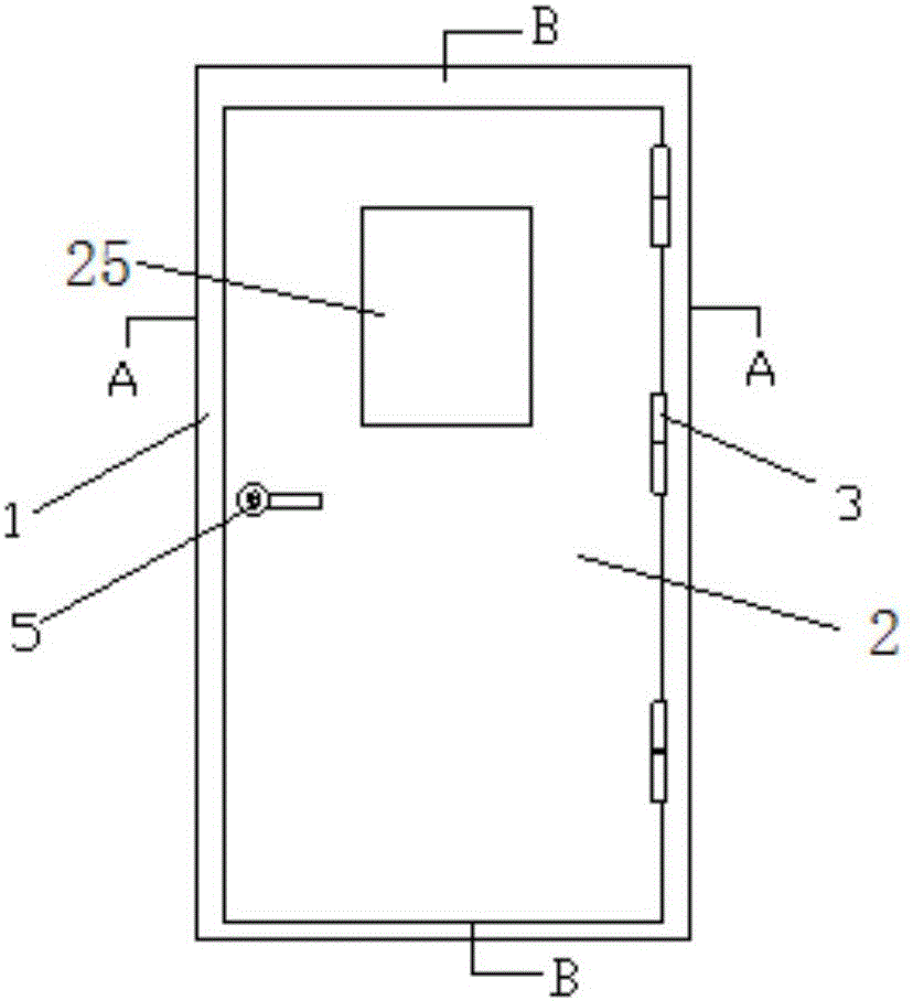
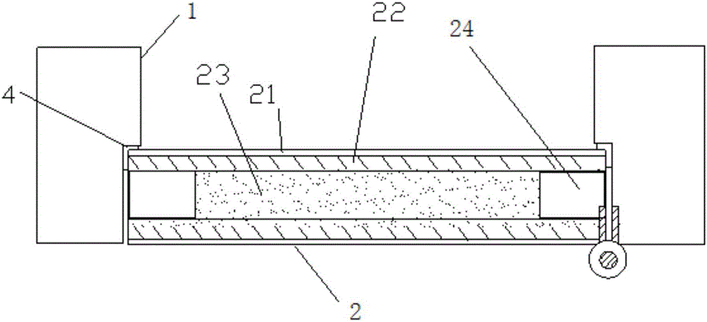
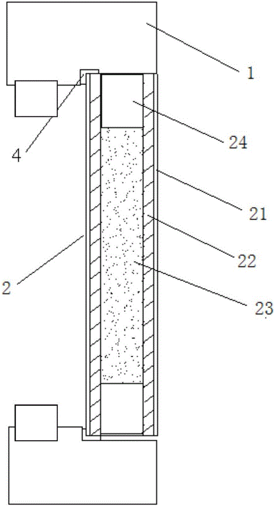
[0022] Such as Figure 1-3 As shown, this embodiment discloses a steel-wood heat-insulated fireproof door, comprising a door frame 1 and a door leaf 2, and the door frame 1 is hinged with the door leaf 2 through a fireproof hinge 3; It is L-shaped, and the door leaf 2 is limited by the L-shaped door frame 2 in the closed state. The door leaf 2 is sequentially provided with plywood 21 , glass magnesium plate 22 , and expanded perlite fireproof board 23 from outside to inside in the thickness direction. The plane size of the expanded perlite fireproof board 23 is smaller than the plane size of the plywood 21 and the glass magnesium flat board 22 . Fire-resistant wood 24 is provided around the expanded perlite fireproof board 23 . There is an L-shaped fireproof expansion seal 4 between the door frame 1 and the door leaf 2. The L-shaped fireproof expansion seal 4 is i...


PUM

PropertyMeasurementUnit
Heightaaaaaaaaaa
Widthaaaaaaaaaa
Thicknessaaaaaaaaaa

Abstract

The invention discloses a thermal insulation fireproof steel-wood door which comprises a door frame and a door leaf. The door frame is hinged to the door leaf through fireproof hinges. The door leaf is provided with plywood, a glass fibre and magnesium cement board and an expanded perlite fireproof plate from outside to the center in the thickness direction. The plane dimension of the expanded perlite fireproof plate is smaller than the plane dimension of the plywood and the plane dimension of the glass fibre and magnesium cement board. Flame retardant wood is arranged around the expanded perlite fireproof plate. The cross sections of four edge frame bodies of the door frame are all in an L shape. The door leaf is limited by the L-shaped door frame in a closed state. L-shaped fireproof expansion sealing elements matched with the L-shaped door frame are arranged between the door frame and the door leaf. Compared with the prior art, the thermal insulation fireproof steel-wood door has the advantages of being high in strength, good in fireproof performance and capable of effectively avoiding deformation of the door leaf.

Description


Claims


Application Information

Patent Timeline
25 Nov 2015
Publication
CN105089461A