
Piston pumps, especially fuel pumps for fuel systems of internal combustion engines

A technology of piston pumps and pistons, which is applied in the direction of charging systems, fuel injection pumps, components of pumping devices for elastic fluids, etc., can solve the problems of strong heating of piston pumps, adverse effects on piston pump performance and durability, etc. Achieve the effect of reducing wear, reducing piston ulceration and reducing vapor bubble formation

Active Publication Date: 2019-03-29
ROBERT BOSCH GMBH
View PDF5 Cites 0 Cited by
  • Summary
  • Abstract
  • Description
  • Claims
  • Application Information

AI Technical Summary

Problems solved by technology

During operation, the piston pump partially heats up strongly, which can adversely affect the performance of the piston pump and / or its durability

Method used


Image

  • Piston pumps, especially fuel pumps for fuel systems of internal combustion engines

Examples


Embodiment Construction

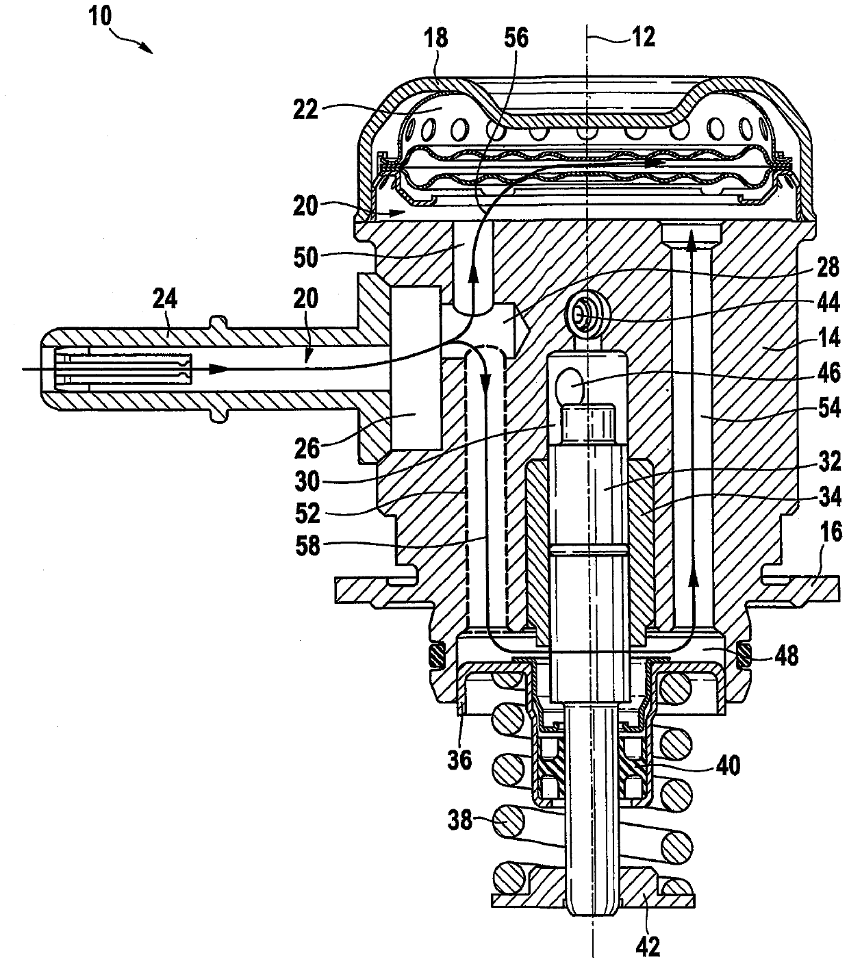
[0015] figure 1 A high-pressure fuel pump, presently embodied as a piston pump 10 , is shown in axial section. The piston pump 10 is an element of a fuel system (not shown), for example a common rail fuel system for an internal combustion engine, also not shown. Piston pump 10 is at least partially rotationally symmetrical about longitudinal axis 12 .

[0016] The piston pump 10 comprises a substantially cylindrical housing 14 which, by means of a flange 16 , can be screwed to a not shown engine block of an internal combustion engine. The piston pump 10 in figure 1 In the upper region, there is a chamber-shaped inlet-side low-pressure zone 20 formed between the arched cover 18 and the upper, substantially flat end face of the housing 14 in the figure, in which a low-pressure zone for A pressure damper 22 damps the pressure fluctuations that occur during the operation of the above-mentioned piston pump 10 .

[0017] Piston pump 10 has an inlet connection 24 in the region on...


PUM


Abstract

The present invention relates to a piston pump (10), in particular a fuel pump for a fuel system of an internal combustion engine, having: an inlet (28), a low-pressure area on the inlet side (20), a piston (32) and a working chamber (30), the working The chamber is delimited by a piston (32), wherein the section of the piston (32) pointing away from the working chamber (30) is arranged in a fluid chamber (48), which is at least temporarily hydraulically connected to said low-pressure area (20). connect. According to the invention, downstream of the inlet (28) at least one first connecting channel (50) branches off to the inlet-side low-pressure zone (20) and at least one second connecting channel (52) branches off to the the fluid chamber (48). The fluid chamber (48) is also connected to the inlet-side low-pressure area (20) by means of at least one third connecting channel (54).

Description

technical field [0001] The invention relates to a piston pump, in particular a fuel pump for a fuel system for an internal combustion engine. Background technique [0002] Piston pumps for fuel systems of internal combustion engines are known on the market, in which piston pumps can be moved axially by means of drives formed by cams or eccentrics. In this case, the required piston restoring force is generated by means of a compression spring. As a result of operation, the piston pump heats up considerably, so that the performance of the piston pump and / or its durability can be adversely affected. Contents of the invention [0003] The problem underlying the invention is solved by the piston pump according to the invention. Advantageous developments are the subject of preferred embodiments. In the following description and drawings, features which are essential to the invention can also be seen, wherein these features can be important to the invention not only individual...

Claims


Application Information

Patent Timeline
Patent Type & Authority Patents(China)
IPC IPC(8): F02M37/04F04B53/14F04B53/08
CPCF02M37/043F02M55/04F02M59/102F02M59/44F04B39/0005F04B39/0061F04B39/123F04B39/128
Inventor T·德尔格A·劳布M·希利加尔特G·泰克T·施塔赫
Owner ROBERT BOSCH GMBH
Learn More