
Hydrostatic piston machine

A technology of piston machine and axial piston machine, which is applied in the field of piston machine, can solve the problems of incompleteness and interruption of suction, and achieve the effect of long service life and increased suction speed

Active Publication Date: 2015-11-25
ROBERT BOSCH GMBH
View PDF8 Cites 1 Cited by
  • Summary
  • Abstract
  • Description
  • Claims
  • Application Information

AI Technical Summary

Problems solved by technology

Finally, an incomplete filling of the working chamber additionally leads to an early interruption of the suction

Method used


Image

  • Hydrostatic piston machine
  • Hydrostatic piston machine
  • Hydrostatic piston machine

Examples


Embodiment Construction

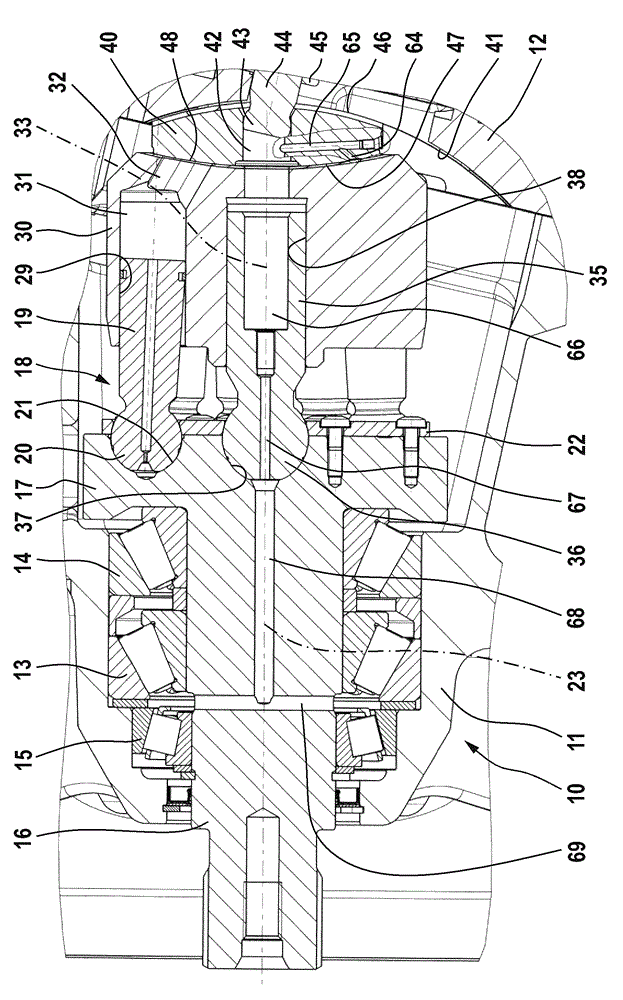
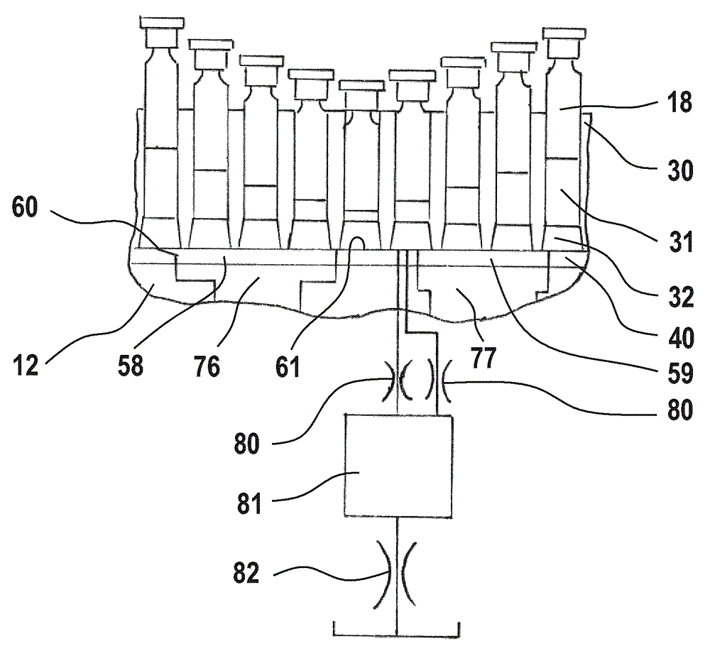
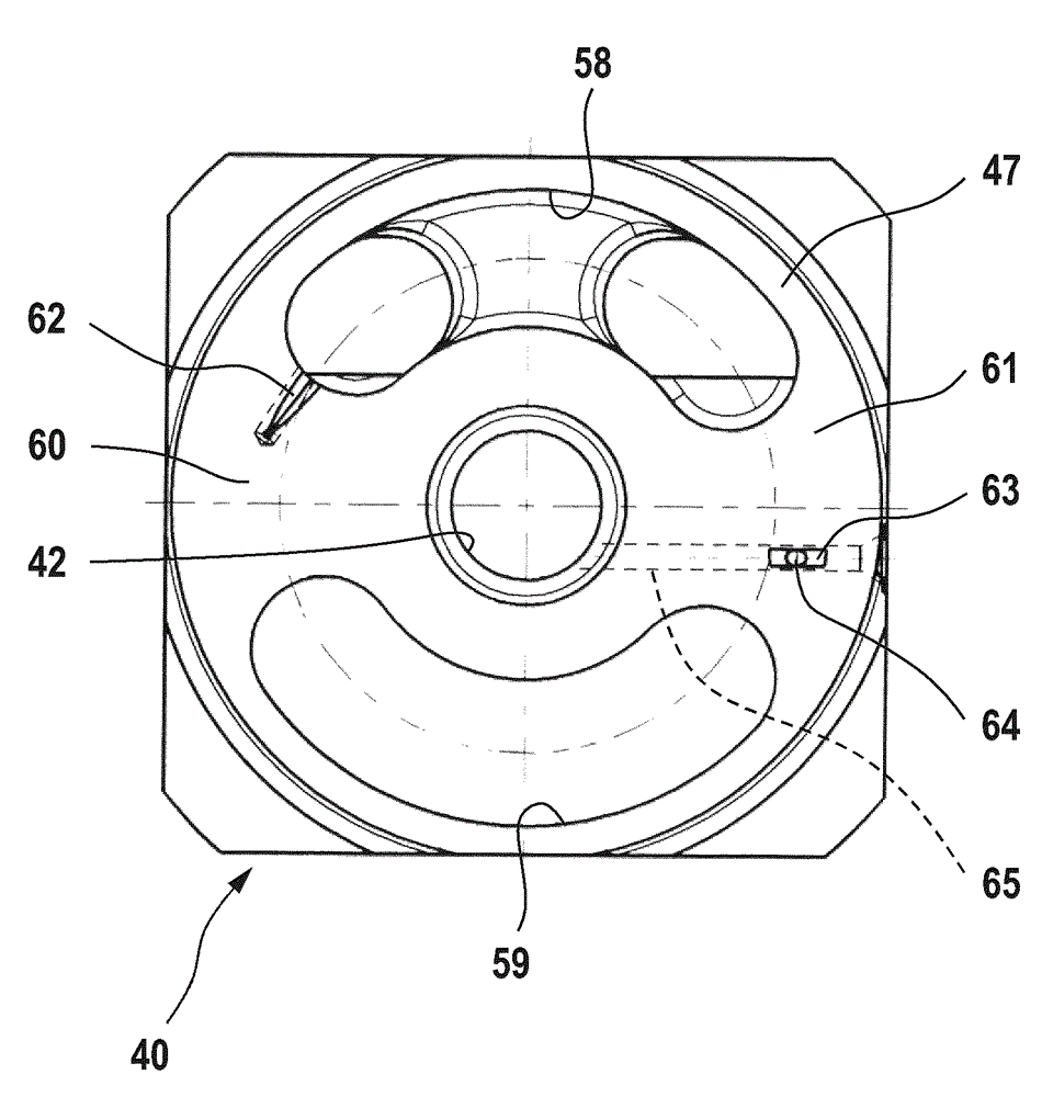
[0037] exist Figures 1 to 3 The hydrostatic axial piston machine shown in detail in the oblique-axis construction is firstly provided for pump operation with hydraulic oil and has a pot-shaped main housing part 11 for short and a cover housing tank connection The housing 10 of the plate 12 on which the high-pressure connection and the low-pressure, suction or tank connection are formed and at the same time the housing for the adjustment mechanism is shown. In the housing pot 11 , a drive shaft 16 is rotatably mounted via three tapered roller bearings 13 , 14 and 15 , which carries a drive flange 17 in one piece. The bearing function is essentially fulfilled by two identical tapered roller bearings 13 and 14 arranged parallel to one another. The smaller tapered roller bearing 15 , which is arranged as a mirror image with respect to the two bearings 13 and 14 , is used for counter-guiding the drive shaft.

[0038] On the drive flange 17 , the piston 18 is supported and held v...


PUM


Abstract

The invention relates to a hydrostatic piston machine having a housing for accommodating return oil, a rotary cylinder body leaning against a control member and having a plurality of cylinder chambers. A piston in the piston machine passes a cylinder chamber afflux part and is alternately connected to a low pressure channel through a low pressure control opening of the control member and connected to a high pressure channel through a high pressure control opening. Two switching regions exist between the low and high pressure control openings on the control member. The piston reverses a motion direction in a dead point, and the corresponding cylinder chamber afflux part sweeps the switching regions of the control member. A pre-control opening exists in the switching regions. The cylinder chamber afflux part switches from the high pressure control opening towards the low pressure control opening of the control member. Before the cylinder chamber afflux part is opened to the low pressure control opening, the cylinder chamber afflux part is connected a low pressure region through a pressure reduction flow path with a first throttling device. The pressure reduction flow path is configured to be pressure reduction cascade. Besides the first throttling device, the pressure reduction flow path has at least a second throttling device in serial connection with the device and has a flow container between the two serial devices.

Description

technical field [0001] The invention relates to a hydrostatic piston machine, in particular a hydrostatic axial piston machine, according to the preamble of patent claim 1 . A hydrostatic axial piston machine is in particular an axial piston machine of inclined-axis construction and is used in particular as a pump. Background technique [0002] A hydrostatic piston machine of this type is known, for example, from EP953767B1. Such hydrostatic piston machines have low-pressure and high-pressure channels which are formed in the main housing or in the web of the housing. The interior of the shell is completely or partially filled with return oil during operation. The hydrostatic piston machine also has a rotating cylinder, which rests on the control element and has a plurality of cylinder chambers, in which the piston is arranged to carry out the stroke movement during operation, and each of them The piston can be connected to the low-pressure channel via the low-pressure con...

Claims


Application Information

Patent Timeline
Patent Type & Authority Applications(China)
IPC IPC(8): F04B1/20F04B11/00
CPCF04B1/20F04B1/24F03C1/0647F04B1/2021
Inventor H.弗里德里希A.比德尔W.迈尔R.罗特
Owner ROBERT BOSCH GMBH
Learn More