pump housing

A pump casing, centrifugal pump technology, applied in the direction of pumps, pump components, non-variable pumps, etc.

Active Publication Date: 2020-03-27
GRUNDFOS HLDG
View PDF4 Cites 0 Cited by
  • Summary
  • Abstract
  • Description
  • Claims
  • Application Information

AI Technical Summary

Problems solved by technology

This can cause problems especially with plastic housings
There is also the problem that the high volume flow needs to be circulated by means of modern heating systems operating at low energy levels in order to supply such pump housings

Method used


Image

  • pump housing
  • pump housing
  • pump housing

Examples


Embodiment Construction

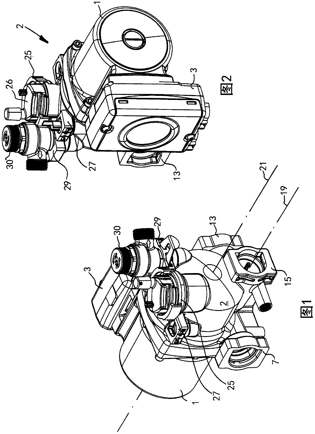
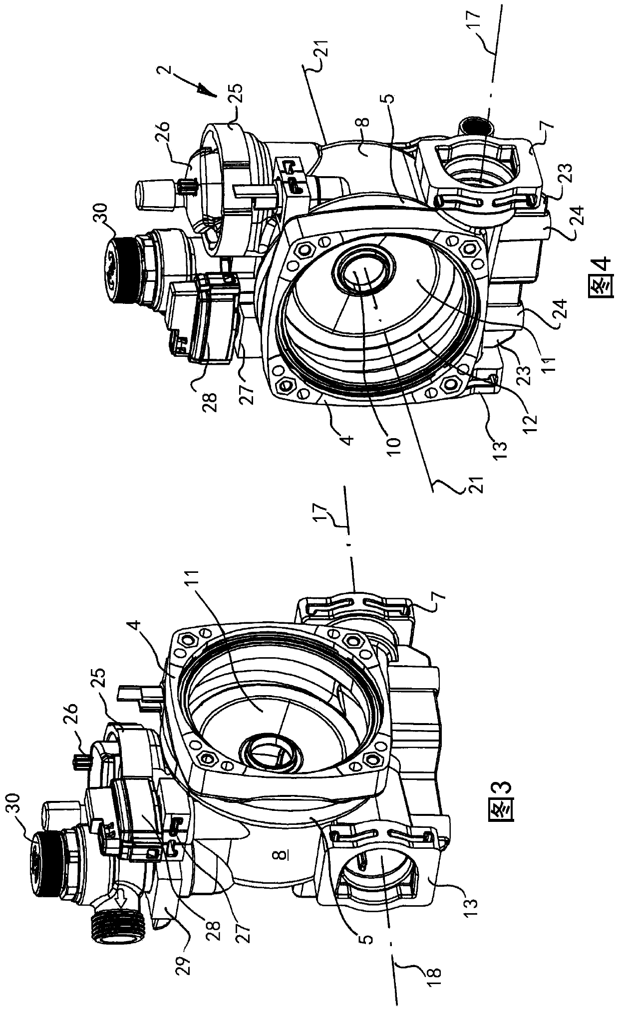
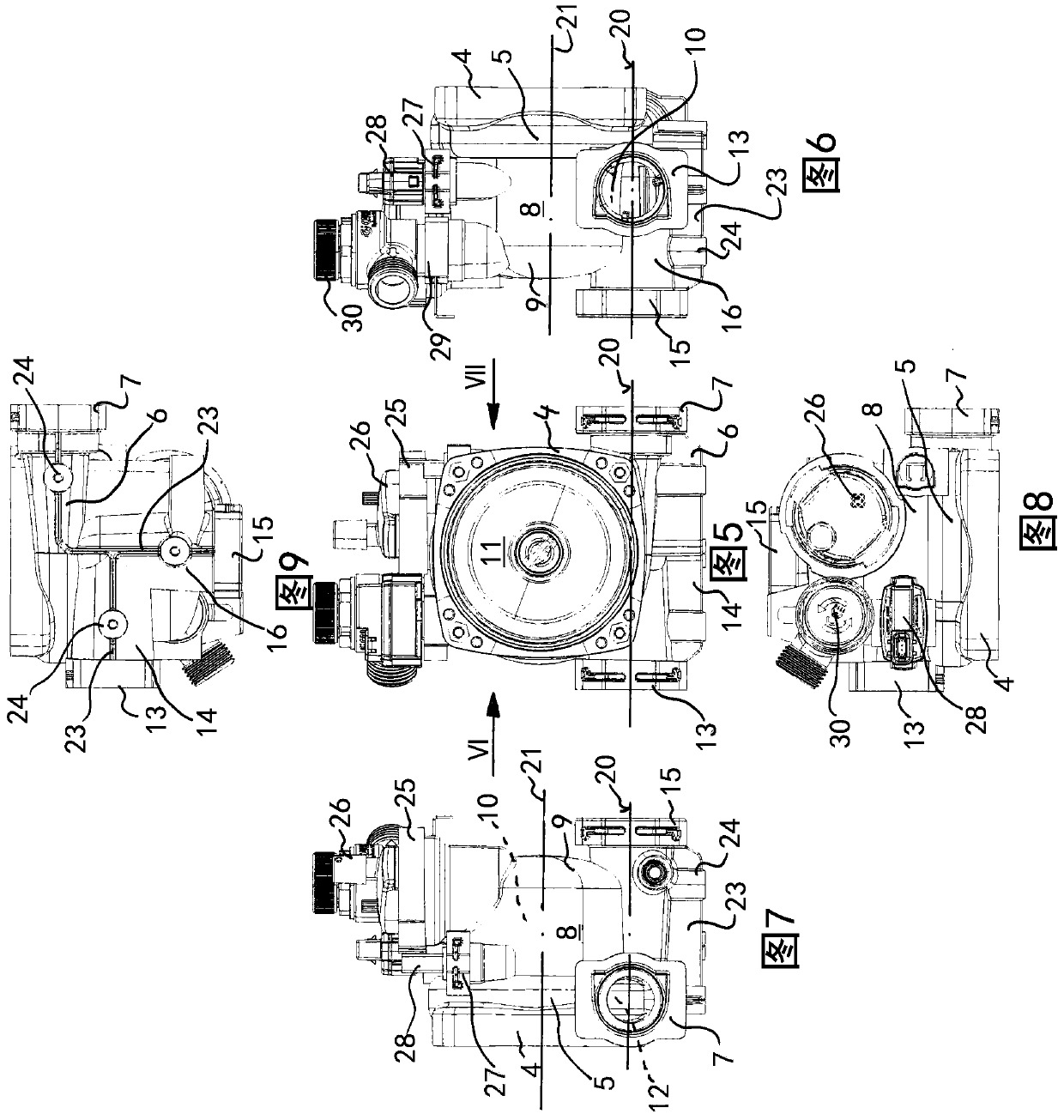
[0065] The heating circulation pump assembly shown in the figure comprises an electric motor 1 ; the electric motor 1 is designed as a wet-running motor, ie comprises a container 32 in which a rotor with a shaft is rotatably mounted. The interior of the container 32 is filled with fluid and said shaft is anchored in the rotor of the motor 1, the free end of which shaft carries a pump impeller 31 which is arranged in the pump housing 2 which is flanged Installed on the driving motor 1, the centrifugal pump assembly shares the driving motor 1. A terminal box 3 is arranged laterally on the drive motor 1, via which not only the coils provided in the stator are connected and connected to the power supply, but also a frequency converter, by means of which the motor 1 can be effectively speed control.

[0066] The pump housing 2 has a substantially beaker-like shape. It comprises a flange 4 designed to be connected to an opposing flange correspondingly designed to the drive motor. ...


PUM

PropertyMeasurementUnit
diameteraaaaaaaaaa

Abstract

The invention relates to a pump housing (2) which is designed as a plastic injection molded part and provided for connection to an electric motor. It has a pressure connection part (7) and at least one a suction connection port (13) extending into a suction chamber. A space for accommodating a pump impeller driven by the electric motor pump, and the pressure connection part (7) extends into the space. The space is connected to the suction chamber. There are two suction connection parts (13, 15) extending into the suction chamber, one of the suction connection part (13) and the pressure connection part (7) are arranged at the opposite sides.

Description

technical field [0001] The invention relates to a pump housing. Background technique [0002] The pump housings of the centrifugal pumps which are the subject of the invention, in particular small and medium-sized heating circulation pumps with an electrical power of up to 250 W, are mass-produced products. The pump housings of such pumps are increasingly being produced not from metal but from plastic and are therefore designed as plastic injection-molded parts. They typically comprise a suction connection and a pressure connection and are designed to receive a centrifugal pump impeller which is seated on the shaft of an electric drive motor which is flanged to the pump housing. [0003] The pump housing forms the suction chamber and thus at least part of a space which is arranged upstream of the suction port of the impeller and is typically designed for smoothing the incoming air flow and for separating air and / or dust, such a pump Housings are considered to be prior art....

Claims


Application Information

Patent Timeline
Patent Type & Authority Patents(China)
IPC IPC(8): F04D29/42F04D29/62
CPCB29C45/33B29C45/44B29L2031/7496F04D29/4293
Inventor L·玛利库瓦B·O·E·多米诺A·蒙斯泰德
Owner GRUNDFOS HLDG
Why Eureka
Try Eureka