
Novel electric-hydraulic proportional overflow valve

An electro-hydraulic proportional and relief valve technology, applied in valve details, valve devices, fluid pressure actuating devices, etc., can solve the pilot valve spool pilot valve seat wear, reduce the performance of the relief valve, and scrap the relief valve and other problems, to achieve the effect of increasing the pressure regulation range, improving the stability, and having a simple structure

Inactive Publication Date: 2015-11-25
FUZHOU UNIV
View PDF5 Cites 6 Cited by
  • Summary
  • Abstract
  • Description
  • Claims
  • Application Information

AI Technical Summary

Problems solved by technology

Due to the change of pressure during the working process of the system, the spool of the pilot valve is often in the open-closed working state, which makes the spool of the pilot valve collide with the seat of the pilot valve frequently, which not only produces noise pollution, but also makes the spool of the pilot valve or The seat of the pilot valve is worn, which affects the sealing, reduces the performance of the relief valve, and even makes the relief valve scrapped. Especially under high pressure, the wear phenomenon is more serious, and the relief valve needs to be replaced frequently, which increases the cost

Method used


Image

  • Novel electric-hydraulic proportional overflow valve
  • Novel electric-hydraulic proportional overflow valve
  • Novel electric-hydraulic proportional overflow valve

Examples


Embodiment Construction

[0030] The present invention will be further described below in conjunction with the accompanying drawings and specific embodiments.

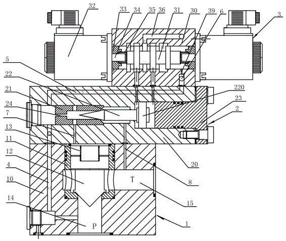
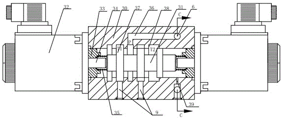
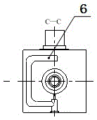
[0031] Such as Figure 1~6As shown, a new type of electro-hydraulic proportional relief valve includes a dynamic relief valve 1, and a pilot valve 2 is tightly fixed on the upper end of the relief valve 1, and the pilot valve 2 includes a pilot valve through which the middle part is transversely penetrated. The valve body 20, the pilot valve seat 21 and the cover plate 23 tightly fixed to the left and right chambers of the pilot valve body 20 respectively, and the valve seat 21 and the cover plate 23 located between the pilot valve seat 21 and the cover plate 23 along the left side of the pilot valve body. 1. The pilot valve spool 22 that slides laterally in the right cavity. One end of the pilot valve spool 22 is tapered and closely fits with the through hole in the middle of the pilot valve seat 21. The other end is provided with a shoulder 2...


PUM


Abstract

The invention relates to a novel electric-hydraulic proportional overflow valve which comprises an overflow valve body, a pilot valve and an electric-hydraulic reversing valve. A main valve seat of the overflow valve body is installed in a main valve body. The outer surface of the main valve seat of the overflow valve body is matched with the main valve body, and the inner surface of the main valve seat of the overflow valve body is matched with a main valve element. Resetting and partial sealing are achieved on the main valve element through a spring. A runner for leading in high-pressure oil is formed in the right end of the valve body of the electric-hydraulic reversing valve. A spring is installed at the right end of the valve element of an electromagnetic valve. Axial movement of the electric-hydraulic reversing valve to the valve element is achieved under common action of spring force, hydraulic force and electromagnetic force. A push cylinder structure is composed of the valve element of the pilot valve, the valve body of the pilot valve and a cover plate; axial movement of the valve element of the pilot valve is controlled through the electric-hydraulic reversing valve; and a large-rigidity pressure-adjusting spring which is traditionally used is replaced for adjusting the pressure of the overflow valve body, and the adjusting pressure of a system is improved. The stability of the overflow valve body is improved by changing the intensity of electromagnetic force, the control precision of the overflow valve body is improved, and the novel electric-hydraulic proportional overflow valve is suitable for high-pressure large-flow hydraulic control systems.

Description

technical field [0001] The invention relates to the field of fluid control, in particular to a novel electro-hydraulic proportional overflow valve. Background technique [0002] Relief valves play the role of pressure regulating valves and safety valves in hydraulic systems, and are widely used in multi-stage pressure control of electro-hydraulic systems such as forging synchronous control systems, machine tool feed systems, automobile steering systems, and ship controllable pitch propellers. . From manual relief valves, electromagnetic relief valves to digital relief valves that appear now, due to the rapid development of high-end hydraulic equipment, higher requirements are put forward for relief valves. The overflow valve with small pressure regulation deviation, small pressure overshoot, and low vibration and noise provides a broad market space. [0003] In the current construction machinery system, the proportional relief valve is divided into direct-acting type and p...

Claims


Application Information

Patent Timeline
Patent Type & Authority Applications(China)
IPC IPC(8): F16K31/36F15B13/02
CPCF15B13/02F16K31/36
Inventor 陈淑梅孙文毅陆小霏黄彬黄国荣王健
Owner FUZHOU UNIV
Learn More