Direct heater

A direct heat engine and heat exchanger technology, applied in the field of thermal engineering, can solve problems such as heat recovery of medium and high temperature wastewater

Active Publication Date: 2015-11-25
HIT HARBIN INST OF TECH KINT TECH
View PDF5 Cites 7 Cited by
  • Summary
  • Abstract
  • Description
  • Claims
  • Application Information

AI Technical Summary

Problems solved by technology

[0016] In order to solve the problem of recovering the heat energy of medium and high temperature wastewater, the present invention provides a direct heat engine

Method used


Image

  • Direct heater
  • Direct heater
  • Direct heater

Examples


Embodiment Construction

[0032] The present invention will be described in further detail below in conjunction with the accompanying drawings and embodiments.

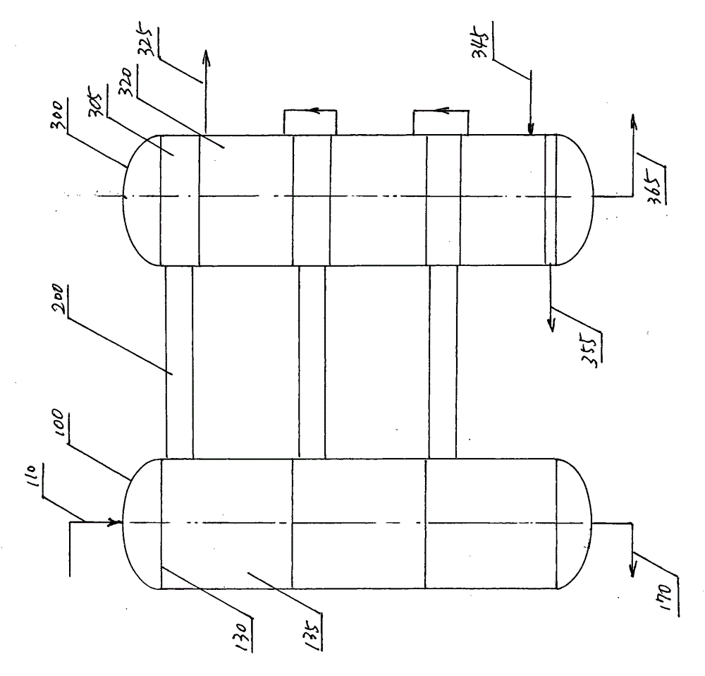
[0033] figure 1 The overall structure diagram of the direct heat engine embodiment of the present invention is given.

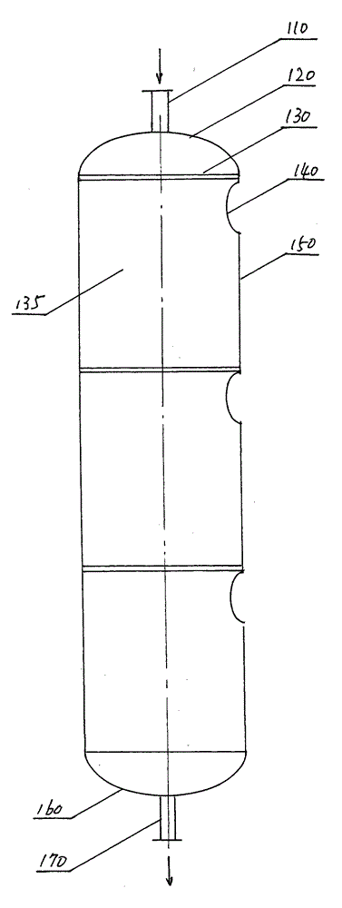
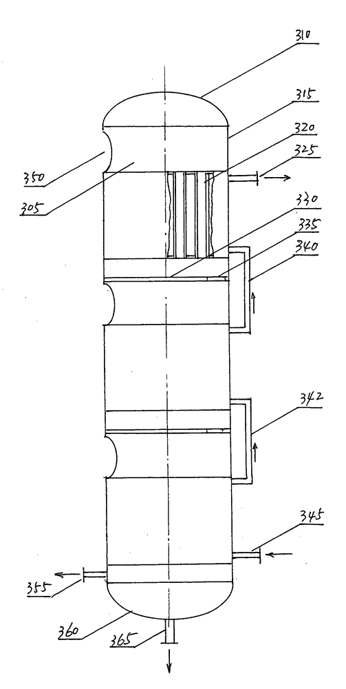
[0034] The overall structure of the embodiment of the direct heat engine of the present invention is divided into left and right parts in appearance: the left side is a vertical evaporator 100, the right side is a vertical condenser 300, and there is a steam channel 200 in the middle.

[0035] The medium and high temperature wastewater enters the evaporator 100 through the water inlet pipe 110, and enters the first evaporation chamber 135 in the evaporator 100 through the first sieve plate 130. The pressure in the evaporation chamber 135 is lower than the saturation pressure corresponding to the temperature of the inlet medium and high temperature wastewater. Therefore, After entering the evaporation chamber 135, the medium-...


PUM


Abstract

The invention discloses a direct heater. The direct heater mainly structurally comprises an evaporator, a condenser and steam channels. The evaporator and the condenser are arranged left and right, and the steam channels are arranged between the evaporator and the condenser. Medium-temperature waste water and high-temperature waste water evaporate in the evaporator to generate steam, and the steam of the evaporator enters the condenser for condensation and heat release through the steam channels. The direct heater is characterized in that the condenser is formed by vertically connecting three dividing wall type heat exchangers in series; the steam channels structurally comprise barrels and fans on the barrels; the barrels are round steam pipelines and are connected between steam outlets of evaporation chambers of the evaporator and steam inlets of condensation chambers of the condenser through flange plates; and the fans on the barrels comprise motors, drive belts, drive shafts and impellers, the impellers are driven by the motors to rotate in the barrels through the drive belts and the drive shafts, and the steam is pushed to flow and flows to the condenser from the evaporator.

Description

technical field [0001] The invention relates to thermal technology, in particular to a direct heating machine. Background technique [0002] my country is already a big country in steel production, and the annual output of steel accounts for 40% of the world's total output. Whether it is steelmaking or ironmaking, a large amount of slag will be produced. Slag is produced along with iron and steel. It is a by-product of iron and steel smelting, and it is also the basic condition for a series of important metallurgical reactions. It directly participates in the physical and chemical reactions and mass and heat transfer processes of iron and steel smelting. It not only affects the output of iron and steel, quality, and is closely related to the consumption of raw materials and energy. [0003] In iron and steel metallurgical furnaces, high-temperature slag at 1400-2000°C is produced. After flowing out through the slag mouth, and then entering the slag flushing launder through...

Claims


Application Information

Patent Timeline
Patent Type & Authority Applications(China)
IPC IPC(8): F24D3/00F22B3/04F28B1/02F28B7/00
Inventor 李伟李金峰师文龙尚德敏
Owner HIT HARBIN INST OF TECH KINT TECH
Why Eureka
Try Eureka