Dynamic compensation method for ultrasonic flow meter

A dynamic compensation and ultrasonic technology, which is applied in the direction of volume measurement, flow/mass flow measurement, liquid/fluid solid measurement, etc., can solve the problem of increasing the amplitude of ultrasonic propagation signals, affecting the accuracy of flow measurement, and abnormal changes in ultrasonic propagation time measurement, etc. problem, to eliminate the deviation of flow calculation and improve the accuracy of flow calculation

Active Publication Date: 2015-11-25
BEIJING INST OF CONTROL ENG
View PDF6 Cites 29 Cited by
  • Summary
  • Abstract
  • Description
  • Claims
  • Application Information

AI Technical Summary

Problems solved by technology

In practical applications, if there is a water hammer effect caused by the instantaneous switch of the valve or residual air bubbles in the pipeline, the amplitude of the ultraso...

Method used


Image

  • Dynamic compensation method for ultrasonic flow meter
  • Dynamic compensation method for ultrasonic flow meter
  • Dynamic compensation method for ultrasonic flow meter

Examples


Embodiment

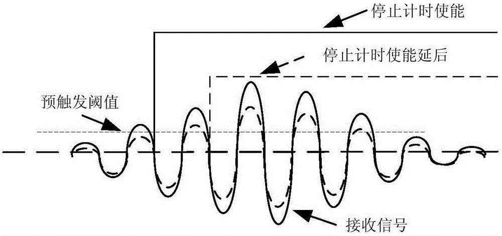
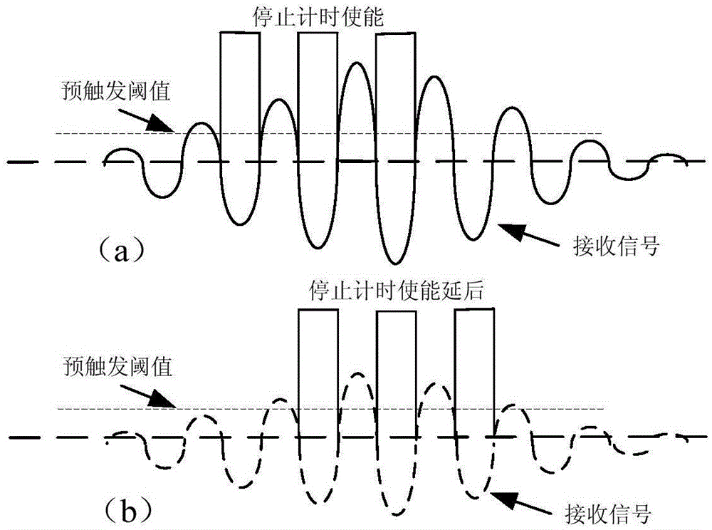
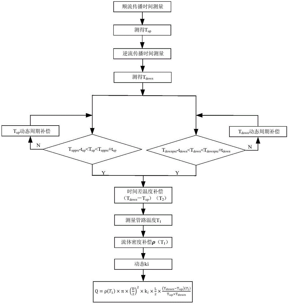
[0110] Utilize the ultrasonic flowmeter to measure the flow Q of the spacecraft propellant, and perform multi-stage dynamic compensation to the measured ultrasonic flowmeter, and the spacecraft propellant uses dinitrogen tetroxide fluid; see image 3 , first the upstream ultrasonic transducer transmits the signal, the downstream ultrasonic transducer receives the received signal, detects the rising edge of three consecutive zero-crossing pulses in the received signal exceeding a pre-triggering threshold as the stop timing enable signal, and the measured time is sequentially respectively recorded as and The measured ultrasonic wave traveling time along the current is denoted as T up ,T up The initial value of Then the downstream ultrasonic transducer transmits the signal, the upstream ultrasonic transducer receives the received signal, detects that the rising edge of three consecutive zero-crossing pulses in the received signal exceeds a pre-trigger threshold, and serves ...


PUM


Abstract

The invention discloses a dynamic compensation method for an ultrasonic flow meter. The dynamic compensation method comprises the step of measuring time dynamic period compensation and further comprises the step of conducting fluid density compensation, the step of conducting time difference temperature compensation of ultrasonic countercurrent spreading time and ultrasonic fair current spreading time, the step of looking up a calibration coefficient dynamically according to a calibration coefficient lookup table established in advance and the step of calculating the flow of multistage dynamic compensation, and therefore measuring time dynamic period compensation is conducted on the problem that ultrasonic spreading time measurement has deviation due to the water attack effect brought by instant opening and closing of a valve or residual bubbles in a pipeline; furthermore, compensation is conducted on the liquid density change caused by the temperature; temperature compensation is conducted on the time difference benchmark treating the influences of the temperature change of an element in a circuit box, the lookup table is established on the calibration coefficient without a constant value, and dynamic looking-up is conducted during flow calculation.

Description

technical field [0001] The invention relates to the technical field of spacecraft propulsion, in particular to a dynamic compensation method for an ultrasonic flowmeter. Background technique [0002] The spacecraft propulsion system completes on-orbit maneuvers such as orbit transfer, attitude control, and position maintenance. Propellants are crucial to ensure the completion of these on-orbit maneuver tasks. Therefore, it is very necessary to monitor and predict the propellants of on-orbit spacecraft . The propellant remaining measurement techniques commonly used at present are gas state equation method (PVT method) and billing method (BK method). Due to the influence of factors such as tank deformation, gas compression factor and gas solubility in liquid, and inaccurate sampling of the temperature and pressure of the on-board tank, the measurement error of the PVT method is greater than 2%. The ground test data of the system does not depend on the stable performance of t...

Claims


Application Information

Patent Timeline
IPC IPC(8): G01F15/02G01F15/00G01F1/66G01F25/00
Inventor 李宗良于洋李湘宁王雪婷焦焱姜涛潘海林耿永兵梁军强张琰
Owner BEIJING INST OF CONTROL ENG
Why Eureka
Try Eureka