Magnetic coupling inductor of interleaving parallel converter and magnetic core

A technology of magnetic core and coupling degree, applied in the direction of transformer/inductor magnetic core, transformer/inductor coil/winding/connection, electrical components, etc., can solve the problems of difficult optimization of magnetic core structure and inflexible adjustment.

Inactive Publication Date: 2015-11-25
SHANGHAI CHINT POWER SYST
View PDF9 Cites 3 Cited by
  • Summary
  • Abstract
  • Description
  • Claims
  • Application Information

AI Technical Summary

Problems solved by technology

[0006] In view of the inflexible adjustment of the coupling degree K and the difficulty in optimizing the magnetic core structure due to the selection of the magnetic core in the design pr

Method used


Image

  • Magnetic coupling inductor of interleaving parallel converter and magnetic core
  • Magnetic coupling inductor of interleaving parallel converter and magnetic core
  • Magnetic coupling inductor of interleaving parallel converter and magnetic core

Examples


Embodiment 1

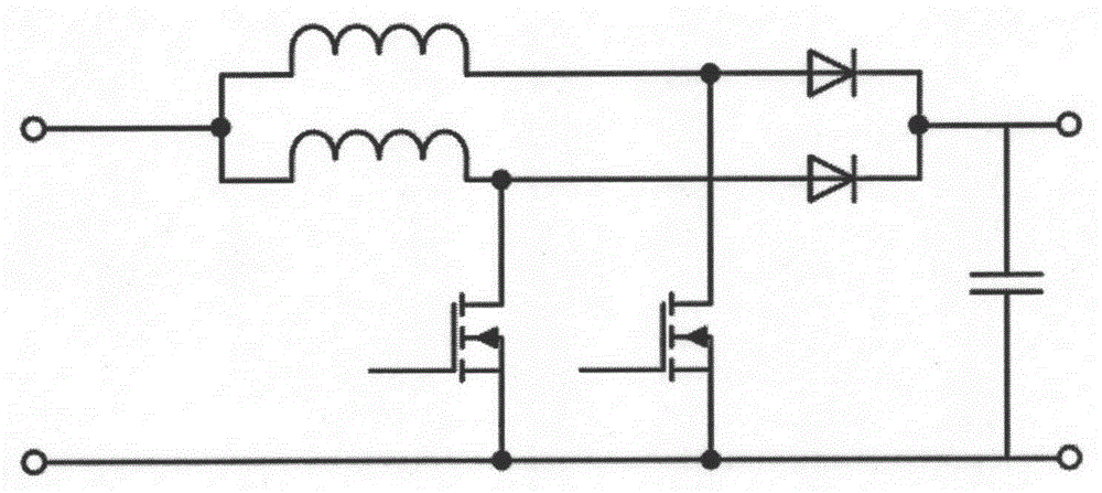
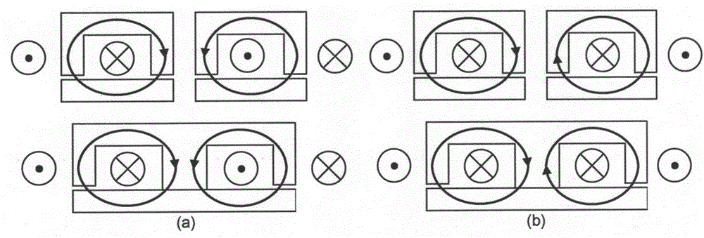
[0029] like Figure 5 As shown, the magnetically coupled inductor 100 in this embodiment includes two coils 105 and a magnetic core. The magnetic core includes an upper plate 101 , a lower plate 102 , two side column magnetic cores 103 and a central column magnetic core 104 . Wherein, the upper plate 101 and the lower plate 102 can be an independent magnetic core with the first magnetic permeability, or a magnetic core with the equivalent first magnetic permeability spliced ​​by multiple magnetic cores, which is used to splice the upper and lower plates The magnetic permeability of the multiple magnetic cores can be the same or different; the two side column magnetic cores 103 can be an independent magnetic core with the second magnetic permeability, or a plurality of magnetic cores spliced ​​together to have the equivalent first magnetic core. The magnetic core of two magnetic permeability, the magnetic permeability of a plurality of magnetic cores that are used for splicing...

Embodiment 2

[0033] refer to Image 6, the magnetically coupled inductor 200 in this embodiment includes two coils 205 and a magnetic core. The magnetic core includes an upper plate 201 , a lower plate 202 , two side column magnetic cores 203 and a central column magnetic core 204 . Wherein, upper plate 201 is made up of the left magnetic core 206 of the left side magnetic core 206 of the upper end 205 of center column magnetic core 204,205 and the right side magnetic core 207 of 205; flush and of the same depth. Lower plate 202 is made up of the lower end 208 of center column magnetic core 204, the left side magnetic core 209 of 208 and the right side magnetic core 210 of 208; , with the same depth. The magnetic cores 206, 207, 209 and 210 have the same size, and can be an independent magnetic core with the first magnetic permeability, or a magnetic core with the equivalent first magnetic permeability formed by splicing multiple magnetic cores, The magnetic permeability of a plurality...

Embodiment 3

[0036] refer to Figure 7 , in this embodiment the magnetically coupled inductor 300 includes two coils 305 and a magnetic core. The magnetic core includes an upper plate 301 , a lower plate 302 , two side column magnetic cores 303 and a central column magnetic core 304 . Wherein, the upper plate 301 is composed of the magnetic core 306 and the upper parts 307 and 308 of the side column magnetic core 303; the upper end of the magnetic core 306 is flush with the upper end of the side column magnetic core 303 and has the same depth. The lower plate 302 is jointly composed of a magnetic core 309 and lower parts 310 and 311 of the side post magnetic core 303 ; the magnetic core 309 is flush with the lower end of the side post magnetic core 303 and has the same depth. The magnetic cores 306 and 309 can be an independent magnetic core with a first magnetic permeability, or a magnetic core with an equivalent first magnetic permeability spliced ​​by multiple magnetic cores, which is ...


PUM


Abstract

The invention relates to a magnetic core. The magnetic core is characterized by comprising an upper magnetic core, a lower magnetic core, an intermediate-column magnetic core and side-column magnetic cores, wherein the upper magnetic core and the lower magnetic core are arranged vertically, the intermediate-column magnetic core is arranged at the middle, the side-column magnetic cores are arranged at the two sides of the intermediate-column magnetic core, the upper magnetic core and the lower magnetic core have first magnetic conductivity, the side-column magnetic cores have second magnetic conductivity, and the intermediate-column magnetic core has third magnetic conductivity. The other technical scheme of the invention provides a magnetic coupling inductor of an interleaving parallel converter. The invention provides a coupling induction magnetic core combination scheme in which magnetic cores having different magnetic materials, different magnetic conductivities and different sizes are matched to one another, thus, the magnetic coupling integrated inductor is wide in magnetic core mode selection range, the coupling degree K is flexible and convenient to adjust, the magnetic core structure of the inductor can be optimized, and mass production cost is reduced.

Description

technical field [0001] The invention relates to a magnetic coupling inductor and a magnetic core thereof for a power converter working in an interleaved parallel mode. Background technique [0002] With the development of power electronics technology, the requirements for power converters are becoming more and more stringent, requiring lower input or output voltage, higher current, faster dynamic response, and smaller size. In order to meet these requirements, new technologies are constantly being proposed and applied. [0003] Interleaved parallel technology was first proposed in the 1960s and has been widely used. The use of interleaved parallel technology can effectively reduce the amplitude of the input and output current ripple; at the same time, several smaller inductors are used to replace the large and bulky main inductor in the traditional converter, which can improve the dynamic response speed of the converter and reduce the inductance The volume increases the po...

Claims


Application Information

Patent Timeline
IPC IPC(8): H01F27/24H01F27/30H02M1/00
Inventor 张玉林王光希朱国忠胡伟张俊
Owner SHANGHAI CHINT POWER SYST
Why Eureka
Try Eureka