Slot antenna and terminal

A slot antenna and terminal technology, applied in slot antennas, antennas, antenna supports/installation devices, etc., can solve problems such as affecting the overall aesthetics of mobile phones, poor transmission and reception, and deterioration of antenna performance.

Active Publication Date: 2015-11-25
NUBIA TECHNOLOGY CO LTD
View PDF5 Cites 32 Cited by
  • Summary
  • Abstract
  • Description
  • Claims
  • Application Information

AI Technical Summary

Problems solved by technology

[0004] However, the above-mentioned prior art has the following disadvantages: one, the slit and grounding destroy the continuity of the metal frame, which affects the overall aesthetic feeling of the mobile phone, and the space required for the antenna design is larger than th

Method used


Image

  • Slot antenna and terminal
  • Slot antenna and terminal
  • Slot antenna and terminal

Examples


Embodiment 1

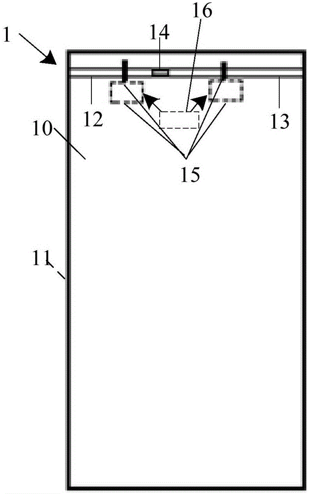
[0069] to combine image 3 with Figure 4 As shown, the embodiment of the present invention provides a slot antenna 1, which is applied to a terminal with an all-metal border. The slot antenna 1 may include: a metal base plate 10, a dielectric substrate 11 located in a metal middle frame, and a The first single-port open-circuit straight seam 12 and the second single-port open-circuit straight seam 13 at the upper end of 10, the ground sheet 14 arranged between the first single-port open-circuit straight seam 12 and the second single-port open-circuit straight seam 13, and the The feed module 15 and the matching circuit 16 at the upper end of the dielectric substrate 11 are described above. in,

[0070] The opening direction of the first single-port open-circuit straight seam 12 is opposite to that of the second single-port open-circuit straight seam 13 , and extends to the edge of the metal bottom plate 10 . There is a gap between them, the first single open straight slit ...

Embodiment 2

[0101] Such as Figure 8 As shown, the embodiment of the present invention provides a terminal 2, and the terminal 2 includes: the slot antenna 1 as described in the first embodiment.

[0102] The slot antenna 1 is used to realize the multi-frequency band bandwidth of the resonant antenna.

[0103] Further, combine image 3 with Figure 4 As shown, the slot antenna 1 may include: a metal bottom plate 10, a dielectric substrate 11 located in a metal middle frame, a first single-port open-circuit straight slit 12 and a second single-port open-circuit straight slit 13 arranged on the upper end of the metal bottom plate 10, and a The ground plate 14 between the first single-port open straight slit 12 and the second single-port open straight slit 13 , the feed module 15 and the matching circuit 16 arranged on the upper end of the dielectric substrate 11 . Wherein, the opening direction of the first single-port open-circuit straight seam 12 is opposite to that of the second singl...


PUM

PropertyMeasurementUnit
Reflection coefficientaaaaaaaaaa

Abstract

The embodiment of the invention discloses a slot antenna, which is applied to a terminal with an all-metal border. The slot antenna comprises a metal bottom plate, a dielectric substrate, a first single-ported open straight slot, a second single-ported open straight slot, a ground lug, a feeding module and a matching circuit, wherein the dielectric substrate is located in a metal middle frame; the first single-ported open circuit straight slot and the second single-ported open circuit straight slot are formed in the upper end of the metal bottom plate; the ground lug is arranged between the single-ported open circuit straight slot and the second single-ported open circuit straight slot; the feeding module and the matching circuit are arranged at the upper end of the dielectric substrate; the open circuit direction of the first single-ported open circuit straight slot is opposite to the open circuit direction of the second single-ported open circuit straight slot, and extends to the edge of the metal bottom plate; a gap is formed between the metal middle frame and the metal bottom plate; the first single-ported open circuit straight slot and the ground lug form a first coupled radiation slot; and the second single-ported open circuit straight slot and the ground lug form a second coupled radiation slot. Meanwhile, the embodiment of the invention further discloses a terminal.

Description

technical field [0001] The invention relates to antenna technology in the field of communication, in particular to a slot antenna and a terminal. Background technique [0002] In recent years, terminals with all-metal borders, such as mobile phones, have been favored by domestic and foreign mobile phone manufacturers due to their beautiful appearance, strong structural strength, and excellent thermal conductivity. However, with the increasing proportion of metal coverage and the evolution requirements of mobile phones with ultra-thin and narrow bezels, it is becoming more and more difficult to realize the multi-band bandwidth of mobile phone antennas. Traditional mobile phone antenna design is difficult to meet the application requirements of metal frame mobile phones, so mobile phones with metal frames have become a major problem for mobile phone manufacturers. [0003] At present, in order to eliminate the influence of the metal frame on the performance of the antenna in ...

Claims


Application Information

Patent Timeline
IPC IPC(8): H01Q13/10H01Q1/24H01Q1/38H01Q23/00
Inventor 李鹏鹏
Owner NUBIA TECHNOLOGY CO LTD
Why Eureka
Try Eureka