Difference setting method and system of excitation system and power system stabilization (PSS) coordination method and system

A technology of excitation system and differential adjustment coefficient, which is applied in the field of power grid, can solve the problems of lack of theoretical calculation, low efficiency of grid voltage stability, and large randomness, so as to improve voltage stability, sensitivity, and overall stability sexual effect

Active Publication Date: 2015-11-25
ELECTRIC POWER RES INST OF GUANGDONG POWER GRID
View PDF4 Cites 17 Cited by
  • Summary
  • Abstract
  • Description
  • Claims
  • Application Information

AI Technical Summary

Problems solved by technology

Under normal circumstances, the selection of the differential coefficient is based on "the voltage differential rate of the parallel point should be set according to 5% to 10%. When the reactive power distribution is stable, take a small value, and the voltage differential rate under the same busbar should be the same" is a principle, but the specific selection is often determined based on experience, lacks theoretical calculations, and is relatively random
Therefore, the traditional method of selecting the adjustment coefficient is not efficient in improving the grid voltage stability.

Method used


Image

  • Difference setting method and system of excitation system and power system stabilization (PSS) coordination method and system
  • Difference setting method and system of excitation system and power system stabilization (PSS) coordination method and system
  • Difference setting method and system of excitation system and power system stabilization (PSS) coordination method and system

Examples


Embodiment Construction

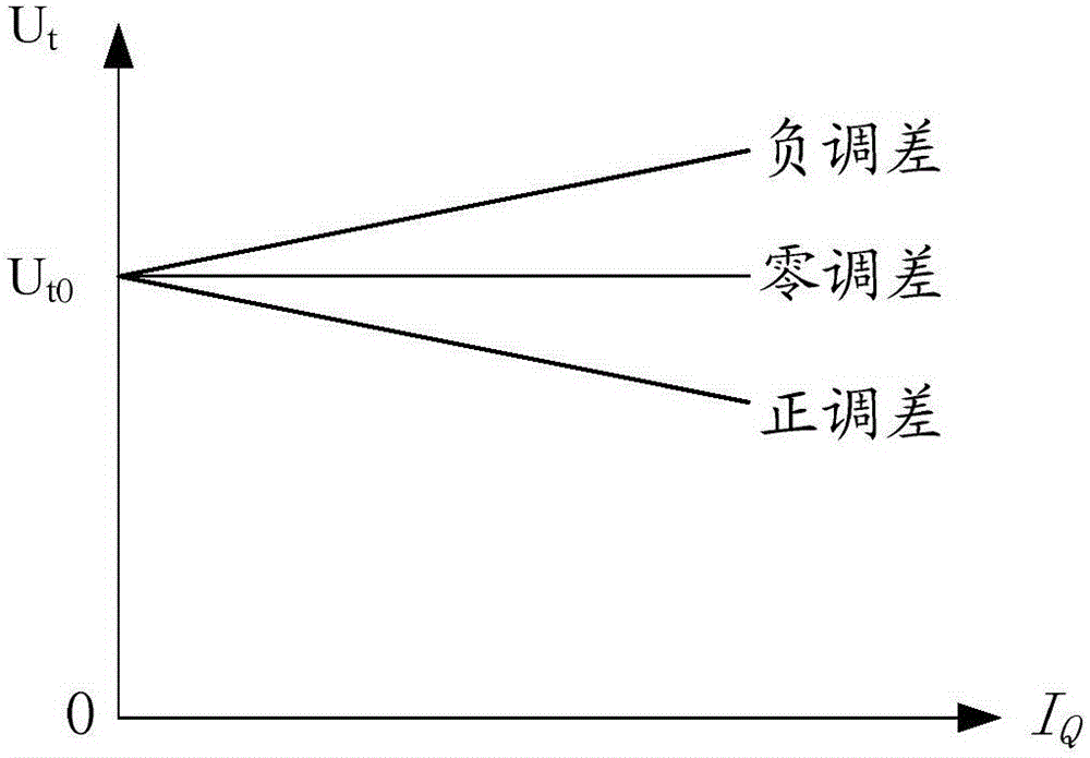
[0041] refer to figure 1 , is the corresponding generator voltage regulation characteristic curve under different conditions, and the difference regulation represents the slope of the characteristic curve. Among them, I Q Indicates reactive current, U t Indicates the terminal voltage of the generator, U t0 It is the corresponding machine terminal voltage when the unit has 0 reactive power. In practical applications, since the measurement of reactive current is cumbersome, reactive power can be directly used instead of reactive current.

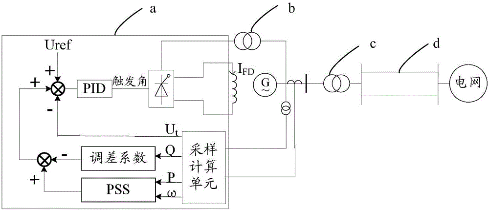
[0042] The superposition position of the difference adjustment in the main loop of the excitation system is as follows: figure 2 As shown, it is directly superimposed on the given value Uref of the main control loop of the excitation system. Among them, a refers to the excitation regulator, b refers to the excitation transformer, c refers to the step-up transformer, and d refers to the line. PID is the excitation PID control algorithm, ...


PUM


Abstract

The invention relates to a difference setting method of an excitation system. The difference setting method comprises the following steps: acquiring power factor of a generator, and calculating a first negative difference coefficient according to the power factor; acquiring a short circuit reactance value of a main transformer of the generator, and calculating a second negative difference coefficient corresponding to the short circuit reactance value with the preset proportion; calculating a corresponding third negative difference coefficient at the preset margin reserved by the total difference of a power generation unit according to the short circuit reactance value; and comparing the first negative difference coefficient, the second negative difference coefficient and the third negative difference coefficient, and updating the maximal value into the current operating difference coefficient. The negative difference coefficients after difference setting are relatively good; under the premises that the stability of the excitation system is not destroyed, and meanwhile reasonable reactive power distribution and stable operation between parallel generator sets are ensured, the contact reactance between the generator and a power grid is reduced; and the sensitivity of the generator to voltage drop of the power grid is improved. Therefore, the voltage stability of the power grid is relatively well improved.

Description

technical field [0001] The invention relates to the technical field of power grids, in particular to a method and system for adjusting the difference of an excitation system and a PSS coordination method and system. Background technique [0002] The differential regulation refers to the rate of change of the terminal voltage of the synchronous generator when the reactive current changes from zero to the rated value under the condition that the power factor of the synchronous generator is equal to zero. The domestic regulations on the polarity of the differential adjustment are as follows: the differential coefficient of the downward-sloping characteristic curve (that is, the voltage decreases with the increase of reactive load) is positive, which is called positive differential adjustment; conversely, the differential adjustment coefficient of the upward-sloping characteristic curve Negative, called negative adjustment. [0003] At present, generators in power plants genera...

Claims


Application Information

Patent Timeline
Patent Type & Authority Applications(China)
IPC IPC(8): H02J3/16H02P9/10
CPCY02E40/30
Inventor 张俊峰苏寅生孙闻盛超赵艳军梅成林朱良合马明王奕陈锐
Owner ELECTRIC POWER RES INST OF GUANGDONG POWER GRID
Why Eureka
Try Eureka