Unlock instant, AI-driven research and patent intelligence for your innovation.

Mems pressure sensor assembly

A technology of pressure sensors and components, applied in the direction of electric solid devices, semiconductor devices, measuring fluid pressure, etc., can solve the problems of over, ceramic packaging and preformed packaging, such as expensive manufacturing

Inactive Publication Date: 2015-11-25
ROBERT BOSCH GMBH +2
View PDF5 Cites 3 Cited by
  • Summary
  • Abstract
  • Description
  • Claims
  • Application Information

AI Technical Summary

Problems solved by technology

For example, the package may define a substrate contact area that exceeds the area available for mounting the pressure sensor
Also, especially when wire bonding is used to electrically connect the package to the circuit / sensor, the package may exceed the height limit of the sensor application
Additionally, ceramic packages and preformed packages are generally expensive to manufacture compared to some other packaging methods

Method used


Image

  • Mems pressure sensor assembly
  • Mems pressure sensor assembly

Examples


Embodiment Construction

[0010] For the purpose of promoting an understanding of the principles of the invention, reference will now be made to the embodiments illustrated in the accompanying drawings and described in the following written description. It should be understood that no limitation of the scope of the invention is intended. It is also to be understood that the invention includes alterations and modifications to the illustrated embodiments and also includes applications of the principles of the invention as would normally occur to one skilled in the art to which this invention pertains.

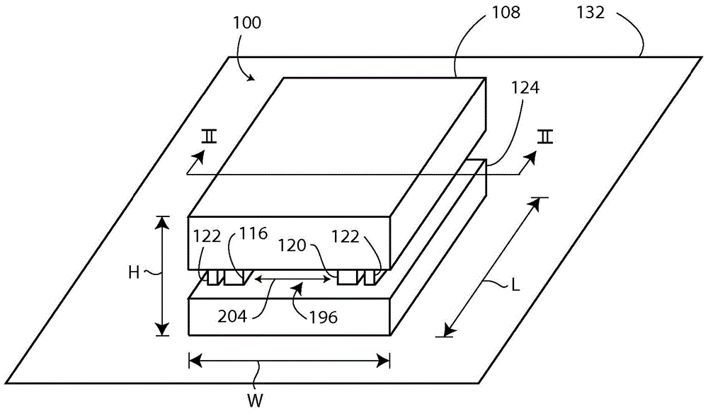
[0011] Such as figure 1 As shown, pressure sensor assembly 100 includes upper die assembly 108 , conductive member 116 , conductive member 120 , bonding member 122 , and lower die assembly 124 . Pressure sensor assembly 100 is shown positioned on a substrate 132 , such as a printed circuit board or any other substrate suitable for mounting electrical components.

[0012] refer to figure 2 , upper die ...


PUM


Abstract

A pressure sensor assembly includes a first die assembly, a second die assembly, and a conducting member. The first die assembly includes a MEMS pressure sensor. The second die assembly includes an ASIC configured to generate an electrical output corresponding to a pressure sensed by the MEMS pressure sensor. The conducting member is positioned between the first die assembly and the second die assembly and is configured and to electrically connect the MEMS pressure sensor to the ASIC.

Description

technical field [0001] The present invention relates generally to semiconductor devices and more particularly to microelectromechanical systems (MEMS) pressure sensors. Background technique [0002] Due to the sensitivity, spatial and temporal resolution and low power requirements exhibited by MEMS devices, microelectromechanical systems (MEMS) have proven to be effective solutions in various applications. Accordingly, MEMS-based sensors such as accelerometers, gyroscopes, acoustic sensors, optical sensors, and pressure sensors have been developed for a wide variety of applications. [0003] MEMS pressure sensors are usually packaged in ceramic or preformed packages. Ceramic and preformed packages work well to accommodate MEMS pressure sensors. However, for some sensor applications, these types of packages are simply too large. For example, the package may define a substrate contact area that exceeds the area available for mounting the pressure sensor. Also, especially w...

Claims


Application Information

Patent Timeline
IPC IPC(8): G01L9/00G01L19/00G01L19/14H01L23/52
CPCG01L19/148B81B2201/0264B81C1/00238B81C2203/0792G01L9/0073G01L19/0061
Inventor A·L·费伊G·奥布赖恩
Owner ROBERT BOSCH GMBH
Features
  • R&D
  • Intellectual Property
  • Life Sciences
  • Materials
  • Tech Scout
  • Unparalleled Data Quality
  • Higher Quality Content
  • 60% Fewer Hallucinations
Learn More