Method and device for treating organic exhaust gas
A technology for organic waste gas and waste gas, applied in separation methods, chemical instruments and methods, waste fuels, etc., can solve secondary pollution and other problems, achieve the effects of increasing mechanical strength, increasing gas-liquid contact area, and improving mass transfer efficiency of fillers
- Summary
- Abstract
- Description
- Claims
- Application Information
AI Technical Summary
Problems solved by technology
Method used
Image

Examples
Example Embodiment
[0049] Example 1
[0050] A method for treating organic waste gas, including the following steps:
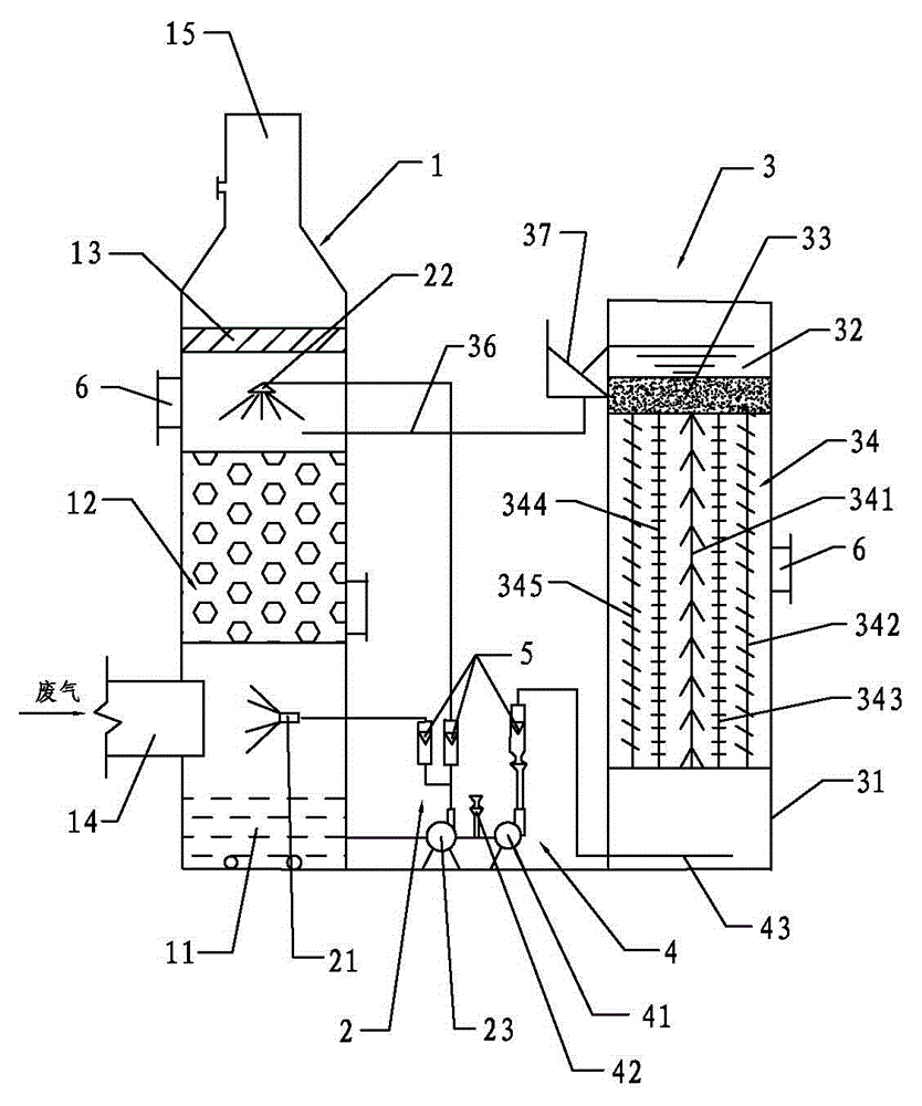
[0051] Step a: Pass the organic waste gas into the packing absorption tower 1, and use the spray head to forward spray the spray liquid to the organic waste gas, and the spray liquid absorbs the organic pollutants in the organic waste gas;
[0052] Step b: The organic waste gas sprayed in step a passes upward through the filler layer 12 of the low resistance filler, and is secondarily absorbed by the spray liquid sprayed downward to obtain a gas-liquid mixture; the filler layer 12 in step b is Multi-faceted hollow ball packing.
[0053] And the spray liquid at the bottom of the packing absorption tower is catalytically oxidized by the catalytic biochemical reactor 3, and the overflow liquid formed by the decomposition of microorganisms passes through the packing layer 12 and then falls back to the bottom of the packing absorption tower 1. The catalytic biochemical reactor 3 is equipped...
Example Embodiment
[0074] Example 2
[0075] The difference between this embodiment and the embodiment 1 is that the packing layer 12 in the step b of this embodiment is a stepped ring packing. The suspended biological filler 34 includes a long strip of far-infrared biological filler 341 and a soft filler 344. The transition metal oxide is cobalt metal oxide, and the natural mineral material is expanded vermiculite.
[0076] The spray width of the first spray head 21 is 60°, the position of the first spray head 21 does not exceed the central axis of the packing absorption tower 1, the spray width of the second spray head 22 is 90°, the second spray The spray range of the head 22 covers the surface of the packing layer 12, and the spray liquid-to-air ratio of the first shower head 21 and the second shower head 22 is 5L / m 3 .
[0077] The rest of the content of this embodiment is the same as that of Embodiment 1, and will be repeated here.
Example Embodiment
[0078] Example 3
[0079] The difference between this embodiment and the embodiment 1 is that the packing layer 12 in the step b of this embodiment is a Pall ring packing. The suspended biological filler 34 includes a long strip of far-infrared biological filler 341 and a semi-soft filler 343. The transition metal oxide is molybdenum metal oxide, and the natural mineral material is a mixture of bentonite and diatomite in a mass ratio of 1:1.
[0080] The catalyzed biochemical reactor 3 is fed with dominant microorganisms that have been cultured and domesticated, and the microorganisms oxidatively degrade the organic matter absorbed by the spray.
[0081] The spray width of the first spray head 21 is 80°, the position of the first spray head 21 does not exceed the center axis of the packing absorption tower 1, the spray width of the second spray head 22 is 100°, and the second spray The spray range of the head 22 covers the surface of the packing layer 12, and the spray liquid-to-a...
PUM
| Property | Measurement | Unit |
|---|---|---|
| Thickness | aaaaa | aaaaa |
| Height | aaaaa | aaaaa |
| Removal rate | aaaaa | aaaaa |
Abstract
Description
Claims
Application Information
 - R&D
- Intellectual Property
- Life Sciences
- Materials
- Tech Scout
- Unparalleled Data Quality
- Higher Quality Content
- 60% Fewer Hallucinations
Browse by: Latest US Patents, China's latest patents, Technical Efficacy Thesaurus, Application Domain, Technology Topic, Popular Technical Reports.
© 2025 PatSnap. All rights reserved.Legal|Privacy policy|Modern Slavery Act Transparency Statement|Sitemap|About US| Contact US: help@patsnap.com