
Rotating disc type vacuum perforating apparatus

A punching device and turntable technology, applied in positioning devices, boring/drilling, drilling/drilling equipment, etc., can solve problems such as laborious, low processing efficiency, and inconvenience

Inactive Publication Date: 2015-12-02
SUZHOU ENOUXI INTELLIGENT TECH CO LTD
View PDF10 Cites 25 Cited by
  • Summary
  • Abstract
  • Description
  • Claims
  • Application Information

AI Technical Summary

Problems solved by technology

[0002] When the existing parts are punched, it is usually necessary to install a fixture on the punching machine body, so that the parts can be positioned on the punching machine body, and this kind of fixture can only clamp one part at a time, so that each time Only one part can be processed, and the processing efficiency is relatively low. After a part is punched, the staff needs to manually remove the part from the fixture, and then manually clamp the next part, which is very inconvenient, time-consuming and laborious.

Method used


Image

  • Rotating disc type vacuum perforating apparatus
  • Rotating disc type vacuum perforating apparatus

Examples


Embodiment

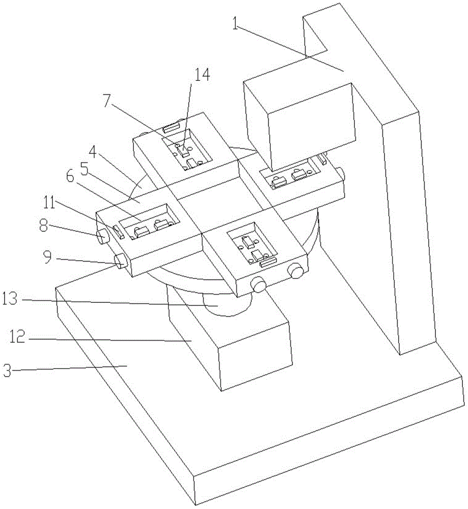
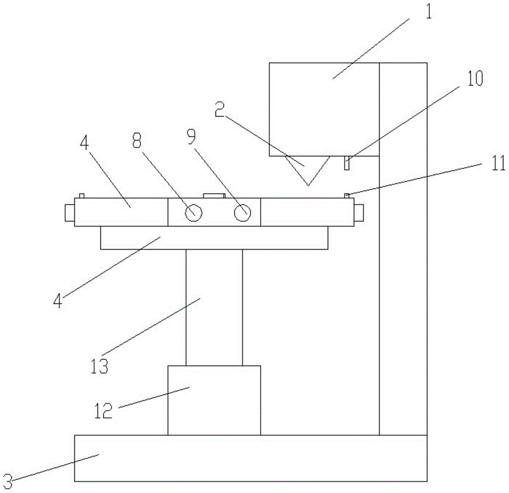
[0017] Embodiment: a rotary table type vacuum punching device, comprising a punching machine body 1, a punching drill bit 2 is installed on the punching machine body, a workbench 3 is arranged on the punching machine body, and a punching machine body is also included. Turntable 4 and several hollow positioning blocks 5, the rotating disk is positioned above the workbench, the positioning block is fixed on the rotating disk, a positioning groove 6 is provided in the middle of the positioning block, and in the positioning groove A plurality of small holes 7 are provided, and the side wall of the positioning groove is provided with an air extraction port 8 and an air charging port 9, and an infrared emitter 10 is fixed on the position of the drilling machine body near the drill bit, and on the positioning block An infrared sensor 11 is fixed, and the infrared sensor is located below the infrared emitter. The parts that need to be punched can be placed through the positioning groo...


PUM


Abstract

The invention discloses a rotating disc typevacuum perforating apparatus which includes a perforating apparatus main body provided with a perforating drill bit thereon and a workbench thereon. The perforating apparatus main body also includes a rotating discand a plurality of hollow positioning blocks. The rotating disc is rotatably positioned above the workbench. The positioning blocks are secured to the rotating disc. The middle of each positioning block is provided with a positioning groove which is provided with a plurality of apertures. The side wall ofeach positioning groove is provided with an air withdrawing opening and an air charging opening. The perforating apparatus main body is fixedly provided thereon with an infrared emitter closeto the position of the drill bit. Each positioning block is fixedly provided with an infrared sensor thereon.Each infrared sensor is arranged below the infrared emitter. The rotating disc type vacuum perforating apparatus can increase the efficiency of perforating and achieve rotary perforating.

Description

technical field [0001] The invention relates to a punching device, in particular to a turntable vacuum punching device. Background technique [0002] When the existing parts are punched, it is usually necessary to install a fixture on the punching machine body, so that the parts can be positioned on the punching machine body, and this kind of fixture can only clamp one part at a time, so that each time Processing can only process one part, and the processing efficiency is relatively low. After a part is punched, the staff needs to manually remove the part from the fixture, and then manually clamp the next part, which is very inconvenient, time-consuming and laborious. [0003] In view of above-mentioned defective, this designer, actively researches and innovates, in order to create a kind of rotating disk type vacuum punching device, makes it more have the utilization value on the industry. Contents of the invention [0004] In order to solve the above technical problems,...

Claims


Application Information

Patent Timeline
IPC IPC(8): B23B39/00B23Q1/25B23Q3/06B23Q3/08
CPCB23B39/00B23Q1/25B23Q3/061B23Q3/088
Inventor 杨文杰
Owner SUZHOU ENOUXI INTELLIGENT TECH CO LTD
Learn More