Check patentability & draft patents in minutes with Patsnap Eureka AI!

Flange clamping device

A clamping device and flange technology, applied in the direction of clamping device, positioning device, clamping, etc., can solve the problems of labor-intensive and low work efficiency, and achieve increased work efficiency, improved space utilization, and convenient and fast clamping. and labor-saving effect

Inactive Publication Date: 2015-12-02
江苏广通管业制造有限公司
View PDF6 Cites 23 Cited by
  • Summary
  • Abstract
  • Description
  • Claims
  • Application Information

AI Technical Summary

Problems solved by technology

[0003] The purpose of the present invention is to provide a flange clamping device, which can automatically clamp flanges with different heights, and flanges with different apertures can be processed on the workbench of this device, so as to solve the above-mentioned problems caused by the prior art. Work efficiency is too low, labor cost

Method used


Image

  • Flange clamping device
  • Flange clamping device
  • Flange clamping device

Examples


Embodiment Construction

[0015] Preferred embodiments of the present invention will be described in detail below in conjunction with the accompanying drawings.

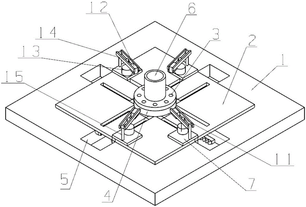
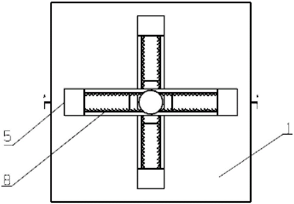
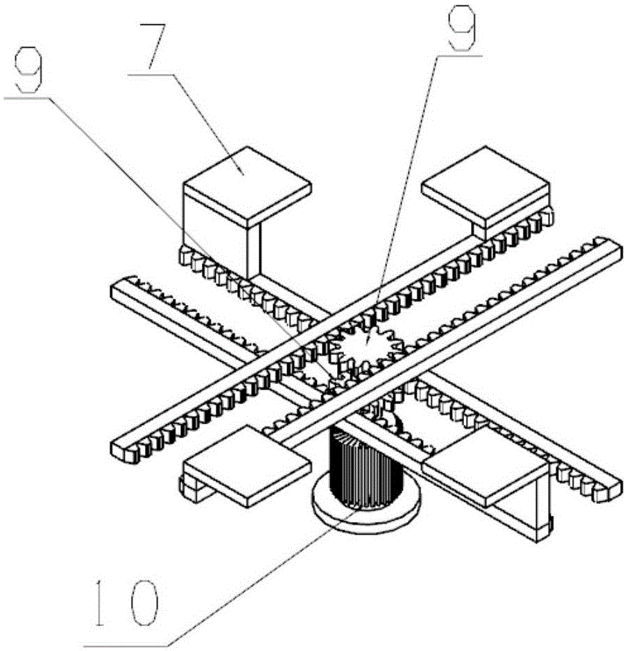
[0016] Figure 1 to Figure 6 A specific embodiment of the present invention is shown: a flange clamping device, including a base 1, a support plate 2, a workbench 4, a clamping base 7, a clamping mechanism 11, two gears 9, and four pairs of opposite teeth Bar 8, single-phase motor 10, two gears 9 and four pairs of opposite racks 8 form a cross-shaped rack and pinion group, and the base 1 is provided with a cross-shaped groove 5 that can place the cross-shaped rack and pinion group, The support plate 2 is arranged on the base 1, and the support plate 2 is provided with two rows of cross-shaped through holes, and the clamping base 7 is slidably connected in the cross-shaped through holes, and the clamping base 7 is fixed on the cross-shaped through holes. On the side wall of the rack 8 of the rack and pinion group, the workbench 4 is arranged ...


PUM


Abstract

The invention discloses a flange clamping device and relates to the technical field of machining. The flange clamping device comprises a base, a flat supporting plate, a workbench, a clamping base, a clamping mechanism, two gears, four racks and a single-phase motor, wherein two of the racks are arranged oppositely, and the other two racks are also arranged oppositely. Through the structural design, a flange body can be clamped rapidly, operation is convenient and fast, and the practicability is high.

Description

technical field [0001] The invention relates to the technical field of machining, in particular to a flange clamping device. Background technique [0002] During the processing of the flange, multiple threaded holes need to be drilled, and the hole diameters of different flanges are different, and the height of the flange itself is also different. The workpiece is placed on the workbench, and the pressure plate is manually pressed on the workpiece, and the pressure plate is fixed with bolts. It is screwed on the workpiece table and processed with a drilling machine and a threaded drill. The work efficiency of this method is too low and it is labor-intensive, so it needs to be improved. Contents of the invention [0003] The purpose of the present invention is to provide a flange clamping device, which can automatically clamp flanges with different heights, and flanges with different apertures can be processed on the workbench of this device, so as to solve the above-mentio...

Claims


Application Information

Patent Timeline
IPC IPC(8): B23Q3/08
CPCB23Q3/08B23Q2703/04
Inventor 徐广林
Owner 江苏广通管业制造有限公司
Features
  • R&D
  • Intellectual Property
  • Life Sciences
  • Materials
  • Tech Scout
  • Unparalleled Data Quality
  • Higher Quality Content
  • 60% Fewer Hallucinations
Learn More