Variable-stiffness robot joint structure

A technology of robot joints and rigidity, which is applied in the direction of manipulators, mechanical equipment, program-controlled manipulators, etc., and can solve problems such as large weight, small output force, and small rigidity

Active Publication Date: 2015-12-02
NORTHEASTERN UNIV
View PDF7 Cites 25 Cited by
  • Summary
  • Abstract
  • Description
  • Claims
  • Application Information

AI Technical Summary

Problems solved by technology

[0004] At present, there are many ways to imitate skeletal muscles, such as electropolymer artificial muscles, shape memory alloys, pneumatic artificial muscles, variable stiffness dri

Method used


Image

  • Variable-stiffness robot joint structure
  • Variable-stiffness robot joint structure
  • Variable-stiffness robot joint structure

Examples


Embodiment 1

[0037]Embodiment 1: Under the condition of constant stiffness, only the joint structure of the present invention is allowed to rotate.

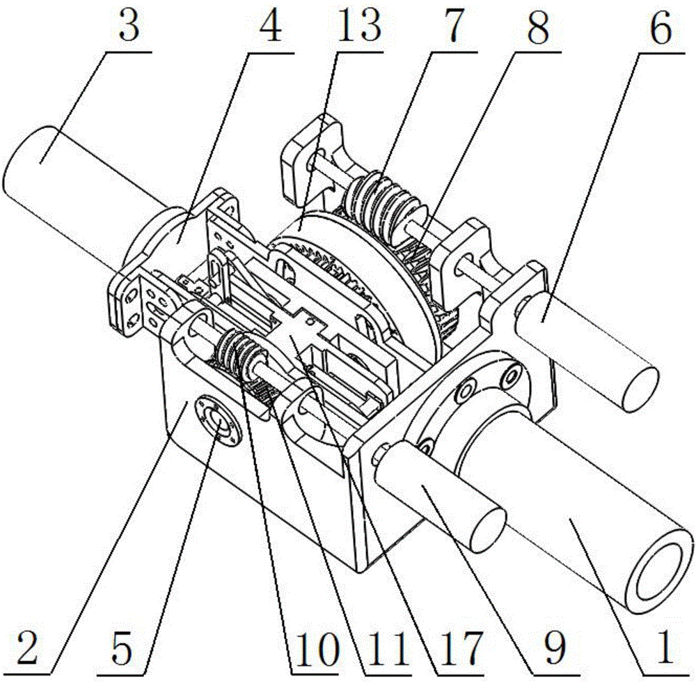
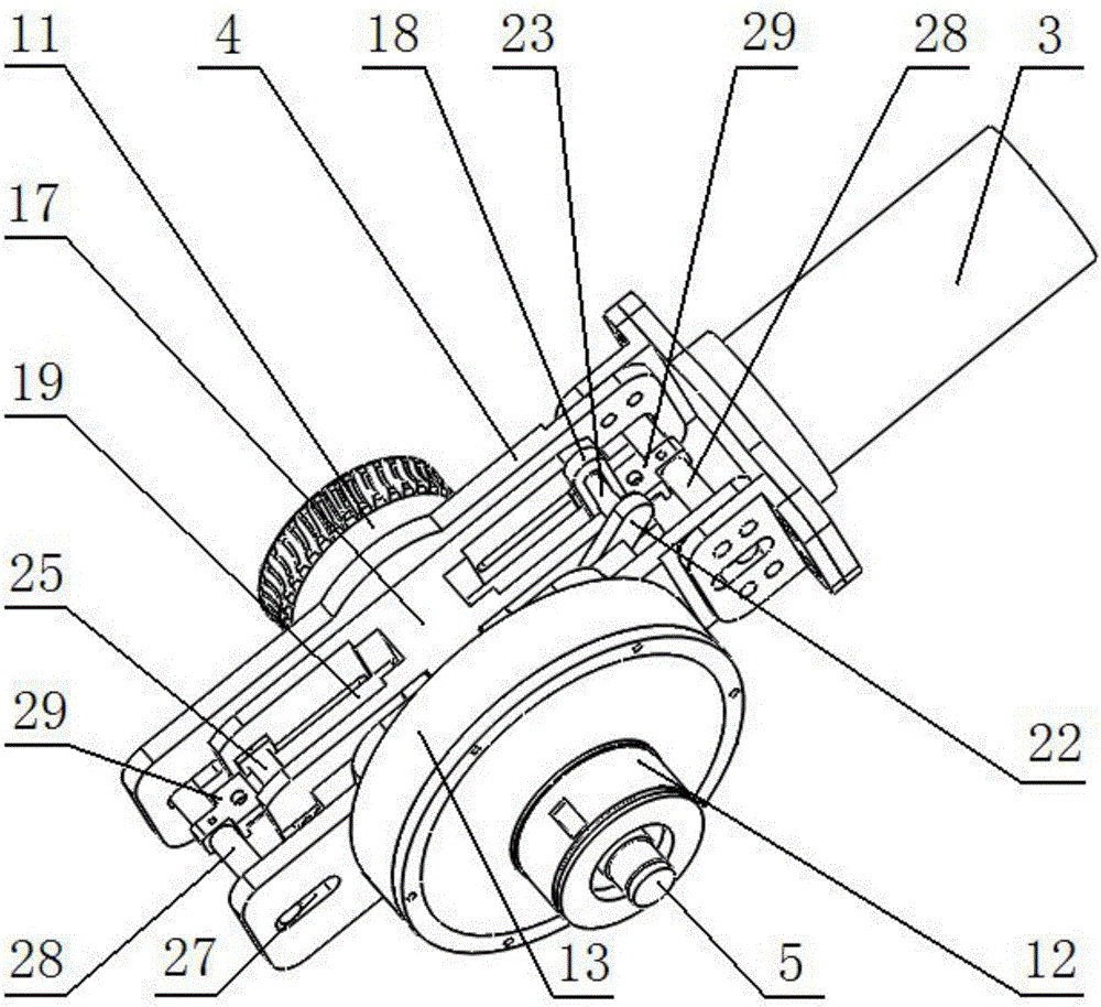
[0038] Start the first drive motor 6 and the second drive motor 9 simultaneously, drive the first worm screw 7 to rotate by the first drive motor 6, and then drive the first worm wheel 8 to rotate, drive the sleeve 12 to rotate by the rotation of the first worm wheel 8, and then drive The inner ring gear 13 rotates; the second drive motor 9 drives the second worm 10 to rotate, and then drives the second worm wheel 11 to rotate, and the rotation of the second worm wheel 11 drives the central shaft 5 to rotate, and then drives the sun gear 14 to rotate;

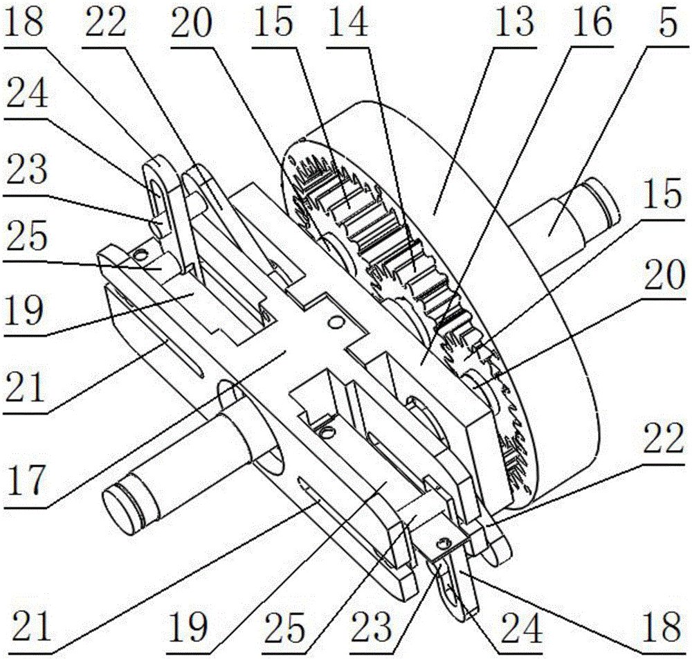
[0039] Let the inner ring gear 13 and the sun gear 14 rotate at the same speed and in the same direction. At this time, the planetary gear 15 only revolves around the sun gear 14 without rotation. Since the planetary gear 15 does not rotate, the variable stiffness actuator does not move, so the...

Embodiment 2

[0040] Embodiment 2: Under the condition that the joint structure of the present invention does not rotate, the stiffness of the joint structure is changed.

[0041] Start the first drive motor 6 and the second drive motor 9 simultaneously, drive the first worm screw 7 to rotate by the first drive motor 6, and then drive the first worm wheel 8 to rotate, drive the sleeve 12 to rotate by the rotation of the first worm wheel 8, and then drive The inner ring gear 13 rotates; the second drive motor 9 drives the second worm 10 to rotate, and then drives the second worm wheel 11 to rotate, and the rotation of the second worm wheel 11 drives the central shaft 5 to rotate, and then drives the sun gear 14 to rotate;

[0042] Make the rotation speed ratio of the ring gear 13 and the sun gear 14 equal to the gear ratio of the sun gear 14 and the ring gear 13, and the ring gear 13 and the sun gear 14 rotate in opposite directions. At this time, the planetary gear 15 only rotates and does n...


PUM


Abstract

The invention relates to a variable-stiffness robot joint structure, belongs to the technical field of bionic robot joints, and is suitable for elbow joints of a bionic robot. Compared with the prior art, the invention designs a new robot joint structure which can simulate the joint with nonlinear variable-stiffness muscle characteristics. A spring piece is taken as a stiffness regulating component and is also taken as a force transmission component, and the stiffness of the spring piece can be changed according to the change of action length. In order to realize the regulation for the action length of the spring piece, through the matching driving of a power component and an action execution component, the action length of the spring piece can be easily regulated through the slippage of a mobile slide rest. Under the condition that the stiffness is not changed, the joint structure can rotate, so that the position regulation of the joint structure under the constant-stiffness condition is realized. Under the condition that the joint structure does not rotate, only the stiffness of the joint structure is changed, therefore the working requirement of the joint under the set stiffness condition is met.

Description

technical field [0001] The invention belongs to the technical field of bionic robot joints, in particular to a variable rigidity robot joint structure, which is suitable for the elbow joint of bionic robots. Background technique [0002] With the development of robot technology, there are more and more human-centered robots, such as rehabilitation robots, wearable robots, intelligent prosthetics, walking robots, etc., and physical human-computer interaction is also increasing. Human-computer interaction safety and environmental adaptability also received wider attention. In order to meet the robot's requirements for high control precision, fast response, and simple control, the motor drive method to ensure the execution accuracy of the robot end has been used by more and more robots. However, it also has the characteristics of high rigidity, and high Stiffness properties are not conducive to the safety requirements of human-computer interaction. [0003] From the perspecti...

Claims


Application Information

Patent Timeline
IPC IPC(8): B25J17/00B25J9/08F16H37/02
Inventor 房立金王颜周生啓
Owner NORTHEASTERN UNIV
Why Eureka
Try Eureka