Sewing machine

A sewing machine and cloth feeding mechanism technology, which is applied to sewing machine components, sewing equipment, sewing machine control devices, etc., can solve the problems of inability to freely control the amount of cloth feeding, and it is not easy to sew patterns.

Active Publication Date: 2015-12-02
JACK SEWING MASCH CO LTD
View PDF7 Cites 30 Cited by
  • Summary
  • Abstract
  • Description
  • Claims
  • Application Information

AI Technical Summary

Problems solved by technology

At present, most sewing machines only use one motor to drive the movement of each mechanism, so there is only one movement track of the feed dog. Therefore, the se...

Method used


Image

  • Sewing machine
  • Sewing machine
  • Sewing machine

Examples


Embodiment 1

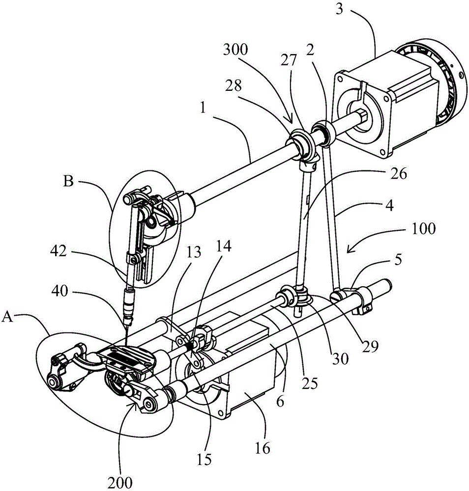
[0067] Embodiment one, as figure 1 As shown, the first transmission unit 100 includes a first eccentric cam 2 or an eccentric bearing fixed on the upper shaft 1, a tooth-lifting rear crank 5 fixed at one end on the tooth-lifting shaft 6, and a tooth-lifting connecting rod 4. The upper end of the tooth lifting connecting rod 4 is rotatably matched with the first eccentric cam 2 or the eccentric bearing, and the lower end of the tooth lifting connecting rod 4 is hinged with the other end of the tooth lifting rear crank 5 . In the present application, the first eccentric cam 2 is fixed on the upper shaft 1; the first eccentric cam 2 includes a first connection part connected with the upper shaft 1 and a second connection part connected with the teeth lifting link 4 , the first connecting part and the second connecting part are arranged eccentrically, so that the center of the upper end of the lifting link 4 does not coincide with the center of the upper shaft 1, so when the first...

Embodiment 2

[0068] Embodiment two, such as Figure 4 As shown, the first transmission unit 100 includes a first connecting rod 20, a second connecting rod 21 and a first slider 22, one end of the first connecting rod 20 is fixed on the upper shaft 1, and the second connecting rod 20 is fixed on the upper shaft 1. One end of the rod 21 is fixed on the lifting shaft 6, the first slider 22 is hinged to the other end of the first connecting rod 20, and is slidably sleeved on the second connecting rod 21, and the second connecting rod 21 Extend along the radial direction of the lifting tooth shaft 6. The upper shaft 1 drives the upper end of the first connecting rod 20 to rotate, so the lower end of the first connecting rod 20 swings back and forth with the axis of the upper shaft 1 as the center line, and is moved by the sliding of the first slider 22 on the second connecting rod 21. Drive the second connecting rod 21 to swing back and forth with the axis of the tooth lifting shaft 6 as the ...


PUM


Abstract

The invention provides a sewing machine. The sewing machine comprises an upper shaft driven by a first motor, a needle bar take-up mechanism arranged at one end of the upper shaft, a lower shaft parallel to the upper shaft, a thread take-off mechanism arranged at one end of the lower shaft, a feed dog frame and a feed dog fixed to the feed dog frame. The upper shaft is connected with the lower shaft through a drive unit. The upper shaft is connected with one end of the feed dog frame through a feed dog lifting mechanism. The sewing machine further comprises a second motor connected with the other end of the feed dog frame through a cloth feed mechanism. The feed dog lifting mechanism and the cloth feed mechanism which form a feed mechanism are driven by the two motors respectively, and therefore the output amount of the cloth feed mechanism can be regulated by regulating the output amount of the second motor, the movement tracks of the feed dog frame and the feed dog can be conveniently changed, and sewing of various patterns can be achieved.

Description

technical field [0001] The invention relates to a garment sewing device, in particular to a sewing machine. Background technique [0002] There are many kinds of sewing machines, including lockstitch sewing machines, overlock sewing machines, chain sewing machines, interlock sewing machines, etc. Among them, lockstitch sewing machines have the highest utilization rate. The sewing machine includes a stabbing mechanism, a thread hook mechanism, a thread take-up mechanism, a feeding mechanism, a winding mechanism, a pressing mechanism, etc., and each mechanism reasonably cooperates with each other to move and work in a cycle to sew up the sewing materials. At present, most sewing machines only use one motor to drive the movement of each mechanism, so there is only one movement track of the feed dog. Therefore, the sewing machine with this structure can only realize one sewing track, so the amount of cloth feeding cannot be freely controlled. , It is not easy to sew various pat...

Claims


Application Information

Patent Timeline
IPC IPC(8): D05B69/10D05B69/02D05B27/02D05B27/24
Inventor 李创潘建国洪志敏杨斌
Owner JACK SEWING MASCH CO LTD
Why Eureka
Try Eureka