Hob mounting structure of shield tunneling machine

A technology for installing structures and shield machines, which is applied in mining equipment, earthwork drilling, tunnels, etc. It can solve problems such as the hob is easy to fall off, and achieve the effect of solving easy fall off, increasing stability, and good stability

Inactive Publication Date: 2015-12-02
CHONGQING TENGHAN IND & TRADE
View PDF0 Cites 16 Cited by
  • Summary
  • Abstract
  • Description
  • Claims
  • Application Information

AI Technical Summary

Problems solved by technology

[0004] The invention provides a shield machine hob installation structure to solve the problem that the hob is easy to fall off

Method used


Image

  • Hob mounting structure of shield tunneling machine
  • Hob mounting structure of shield tunneling machine
  • Hob mounting structure of shield tunneling machine

Examples


Embodiment 1

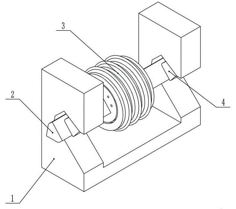
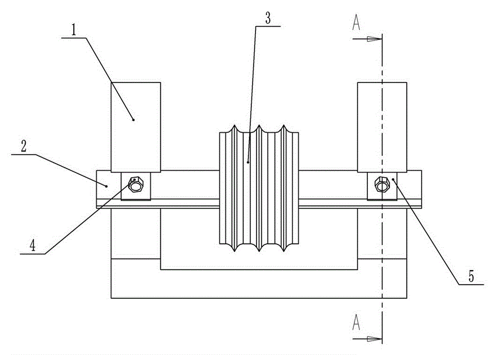
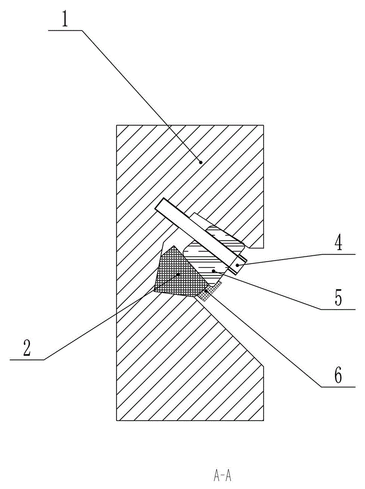
[0023] This embodiment provides a shield machine hob installation structure, such as figure 1 , figure 2 As shown, it includes a knife seat 1, a hob shaft 2, a hob 3, a wedge block 5 and a high-strength bolt 4. A groove is opened on the knife seat 1, and the hob shaft 2 and the wedge block 5 are accommodated in the groove. like image 3 As shown, the cross section of the hob shaft 2 is wedge-shaped, which can ensure that the hob shaft 2 cannot rotate in the groove of the tool holder 2, as shown in Figure 4 As shown, the wedge block 5 is provided with a through hole, and the diameter of the through hole is slightly larger than the outer diameter of the screw rod of the high-strength bolt 4 and smaller than the diameter of the bolt head of the high-strength bolt 4 . Additionally, if image 3 As shown, a stopper 6 is welded on the wedge block 5, and the stopper 6 has a good limiting effect on the hob shaft 2, reduces the vibration of the hob shaft 2, and prevents the hob sha...

Embodiment 2

[0028] This embodiment provides a shield machine hob installation structure, such as Figure 5 As shown, it includes a knife seat 1 , a hob 3 , a first wedge 8 , a second wedge 9 and a hob shaft 2 for fixing the hob 3 . The knife seat 1 is provided with threaded holes matching the high-strength special-shaped bolts 7, and the knife seat 1 is also provided with grooves for accommodating the hob shaft 2, the first wedge block 8 and the second wedge block 9, and the hob The cross section of shaft 2 is wedge-shaped. The hob shaft 2 is located between the first wedge block 8 and the second wedge block 9 and abuts against each other. like Image 6 As shown, the special-shaped bolt 7 includes a bolt head 700, a pressure plate 701 and a screw rod 702 connected in sequence, the bolt head 700, the pressure plate 701 and the screw rod 702 are integrally formed, and the second wedge block 9 is welded with a stopper 6 . The special-shaped bolt 7 is stuck between the first wedge block 8 ...


PUM


Abstract

The invention belongs to the technical field that the whole section is cut simultaneously by one rotary drill, and particularly discloses a hob mounting structure of a shield tunneling machine. The hob mounting structure of the shield tunneling machine comprises bolts, a hob, a tool apron and a hob shaft used for fixing the hob, and further comprises wedge blocks, wherein threaded holes matched with the bolts are formed in the tool apron; grooves for accommodating the hob shaft and the wedge blocks are further formed in the tool apron; a cross section of the hob shaft is wedge-shaped; through holes are formed in the wedge blocks; the diameter of a bolt head of each bolt is larger than the diameter of each through hole, and the outer diameter of a screw of each bolt is smaller than the diameter of each through hole. Besides, the hob mounting structure further comprises stop blocks fixed on the wedge blocks, sealing plugs are further arranged on the tool apron, and pull rings are arranged on the sealing plugs. Compared with a traditional hob mounting structure of the shield tunneling machine, the hob mounting structure of the shield tunneling machine adopts a newly added design of the wedge blocks, the stability of the hob shaft is greatly improved under the locking action of the bolts on the wedge blocks, and the problem that the hob is likely to fall off is effectively solved.

Description

technical field [0001] The invention belongs to the technical field of simultaneously cutting an entire section by a rotary drill bit, and in particular relates to a hob installation structure of a shield machine. Background technique [0002] The shield machine is a special construction machine for tunneling. The modern shield machine integrates optical, mechanical, electrical, hydraulic, sensing and information technologies. It has the functions of excavating and cutting soil, conveying soil, assembling tunnels, lining and Measurement-guided deviation correction and other functions involve multiple disciplines such as geology, civil engineering, machinery, mechanics, hydraulics, electricity, control and measurement. Moreover, the "tailor-made" design and manufacture according to different geological conditions requires extremely high reliability. Shield machines have been widely used in subway, railway, highway, municipal, hydropower and other tunnel projects. [0003] D...

Claims


Application Information

Patent Timeline
Patent Type & Authority Applications(China)
IPC IPC(8): E21D9/08
Inventor 丁丽霞
Owner CHONGQING TENGHAN IND & TRADE
Why Eureka
Try Eureka