Novel honeycomb seal rotor structure

A technology of honeycomb sealing and rotor structure, which is applied in the direction of engine sealing, engine components, mechanical equipment, etc., and can solve the problem of affecting the sealing and damping of honeycomb seals, reducing the energy dissipation of honeycomb seals, and the energy dissipation of honeycomb cores Insufficient and other problems, to achieve the effect of reducing the through effect, promoting the separation of the boundary layer, and efficiently cutting the effect

Active Publication Date: 2015-12-02
SHENYANG AEROSPACE UNIVERSITY
View PDF8 Cites 3 Cited by
  • Summary
  • Abstract
  • Description
  • Claims
  • Application Information

AI Technical Summary

Problems solved by technology

Therefore, the smooth rotor leads to insufficient energy dissipation of the honeycomb core, and the vortex formed in the honeycomb core is smal

Method used


Image

  • Novel honeycomb seal rotor structure
  • Novel honeycomb seal rotor structure
  • Novel honeycomb seal rotor structure

Examples


Example Embodiment

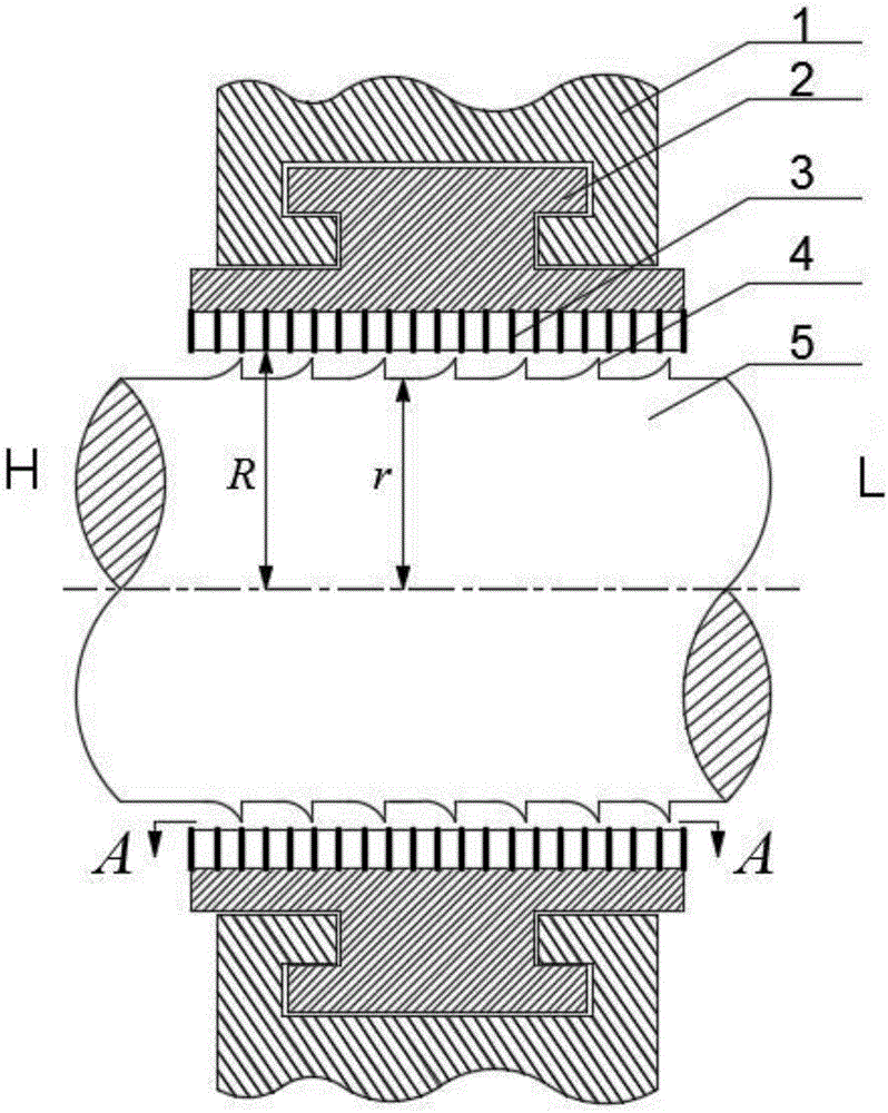
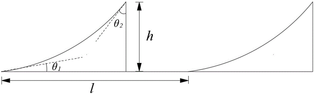
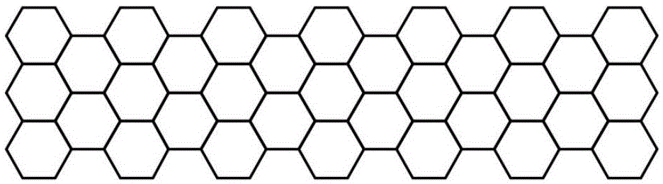
[0017] like Figure 1-Figure 3 Shown: a new type of honeycomb sealed rotor structure, including a sealing sleeve 1, a sealing body 2, an annular concave arc wedge-shaped boss 4, a honeycomb belt 3 and a rotor 5. The sealing body 2 is installed on the sealing sleeve 1 through the T-shaped groove, and the sealing body 2 is provided with a honeycomb belt 3 in the circumferential direction. The sealing sleeve 1, the sealing body 2 and the honeycomb belt 3 all belong to the stator components. The rotor 5 is located in the annular cavity formed by the honeycomb belt 3 . The rotor 5 is axially provided with a plurality of groups of annular concave arc wedge-shaped bosses 4 on its circumferential surface. The included angle θ between the arc surface of the annular concave arc wedge-shaped boss 4 and the surface of the rotor 5 1 =15°, the included angle θ with the vertical surface of the boss 2 =30°, the radial height h of the annular concave arc wedge-shaped bosses is 0.6 times th...


PUM

PropertyMeasurementUnit
Wall thicknessaaaaaaaaaa

Abstract

The invention discloses a novel honeycomb seal rotor structure. The novel honeycomb seal rotor structure comprises a sealing sleeve, a sealing body, annular concave arc wedge bosses, a honeycomb belt and a rotor. The sealing body is mounted on the sealing sleeve; and the honeycomb belt is peripherally arranged on the sealing body. The rotor is positioned in an annular cavity formed by the honeycomb belt. The rotor is provided with multiple sets of annular concave arc wedge bosses on the peripheral surface in the axial direction. Included angles theta1 between arc surfaces of the annular concave arc wedge bosses and the surface of the rotor are not bigger than 45 degrees and not smaller than 5 degrees; included angles theta2 between vertical surfaces of the bosses and the surface of the rotor are not bigger than 45 degrees and not smaller than 5 degrees; radial heights h of the annular concave arc wedge bosses are 0.2-0.6 times of sealing radius gaps (R-r); and axial gaps 1 between the adjacent annular concave arc wedge bosses are 0.5-3 times of honeycomb edge distances. The novel honeycomb seal rotor structure promotes the boundary layer separation of honeycomb seal gap jet fluids, so that honeycomb cells fully exert an energy loss effect; and meanwhile, the concave arc wedge boss structures increase the flowing resistance of the seal gap jet fluids to reduce the direct connection effect causing the sealing leak.

Description

technical field [0001] The invention relates to a dynamic sealing structure in a rotating machine, in particular to a novel honeycomb sealing rotor structure. Background technique [0002] Honeycomb seals are key components of rotating machinery such as aero-engines, steam turbines, and compressors. Compared with the traditional labyrinth seal, the honeycomb seal not only has better sealing characteristics, but also has better rotor dynamic characteristics. The honeycomb seal allows application under high pressure differential conditions without increasing the size of the seal, and has high safety and reliability. Therefore, honeycomb seals are widely used in rotating machinery in aerospace, electric power, petrochemical and other industries. [0003] The honeycomb seal is mainly composed of a sealing sleeve, a sealing body, a honeycomb belt and a rotor, and the honeycomb belt is composed of hexagonal small honeycomb holes. The flow field characteristics and sealing mecha...

Claims


Application Information

Patent Timeline
IPC IPC(8): F16J15/16
Inventor 赵欢孙丹艾延廷蒋泽乾王良全王猛飞
Owner SHENYANG AEROSPACE UNIVERSITY
Why Eureka
Try Eureka