Wavefront sensor and wavefront measuring method

A wavefront sensor and wavefront measurement technology, applied in measurement devices, instruments, optical devices, etc., can solve the problems of difficulty in manufacturing random coded amplitude gratings, and achieve the effects of low manufacturing cost, high interference contrast, and large size

Active Publication Date: 2015-12-02
SHANGHAI INST OF OPTICS & FINE MECHANICS CHINESE ACAD OF SCI
View PDF4 Cites 15 Cited by
  • Summary
  • Abstract
  • Description
  • Claims
  • Application Information

AI Technical Summary

Problems solved by technology

However, in randomly coded hybrid gratings, the fabrication of randomly coded amplitude gratings is difficult

Method used


Image

  • Wavefront sensor and wavefront measuring method
  • Wavefront sensor and wavefront measuring method
  • Wavefront sensor and wavefront measuring method

Examples


Embodiment Construction

[0026] The present invention will be further described below in conjunction with the examples and drawings, but the examples should not limit the protection scope of the present invention.

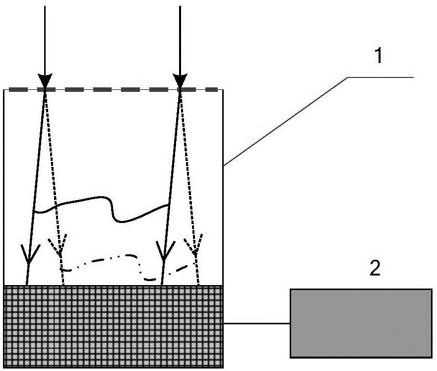
[0027] A wavefront sensor 1, comprising a two-dimensional randomly coded hybrid grating 101 and a detector 102;

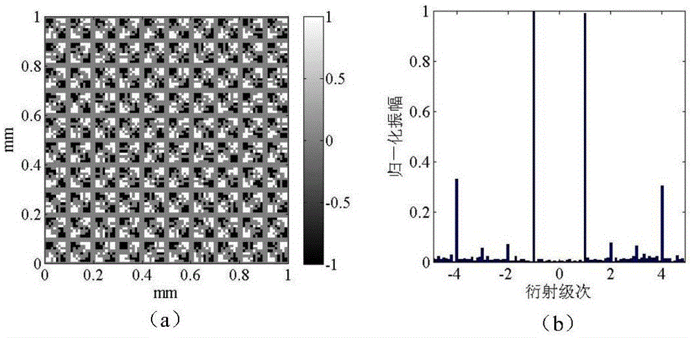
[0028] The two-dimensional randomly coded hybrid grating 101 is a two-dimensional grating with the same grating period in the x and y directions, and is composed of a randomly coded amplitude grating 1011 with a period of 50 μm and a checkerboard phase grating 1012 with a period of 100 μm. The period T of the grating 101 is 100 μm, the central wavelength of the checkerboard phase grating 1012 is 532 nm, the duty cycle is 50%, the phase change of adjacent phase units at the central wavelength is π, the distance between the detector CCD102 and the grating 101 The spacing is 1 cm, and the aperture of the wavefront sensor 1 is 1 cm.

[0029] The randomly coded amplitude grating 10...


PUM


Abstract

A wavefront sensor and a wavefront measuring method are disclosed. The wavefront sensor comprises a two-dimensional random coding mixing raster and a detector, wherein the two-dimensional random coding mixing raster comprises a random coding amplitude raster and a chessboard type phase raster. The pixel dimension of the random coding amplitude raster, the processing difficulty is reduced, and the wavefront measuring precision is not affected.

Description

technical field [0001] The invention relates to wavefront measurement, in particular to a wavefront sensor and a wavefront measurement method. Background technique [0002] Wavefront measurement technology is playing an increasingly important role in the fields of modern physics, biomedicine and engineering technology. Grating shearing interference wavefront measurement technology has the advantages of no need for reference wavefront, anti-environmental interference, and large measurement dynamic range. It has been widely used in the fields of beam collimation measurement, optical system wave aberration measurement, and optical component surface shape measurement Applications. [0003] An improved Hartmann mask is composed of a crossed grating with a duty ratio of 2 / 3 and a phase grating with a duty ratio of 1 / 2, wherein the period of the phase grating is twice that of the crossed grating, the combination The grating eliminates the 3rd order and its multiple diffraction or...

Claims


Application Information

Patent Timeline
Patent Type & Authority Applications(China)
IPC IPC(8): G01B9/02
Inventor 李杰唐锋王向朝戴凤钊
Owner SHANGHAI INST OF OPTICS & FINE MECHANICS CHINESE ACAD OF SCI
Why Eureka
Try Eureka