An optical system for angular velocity measurement

An optical system and angular velocity technology, applied in the field of optical systems, can solve problems such as complex control systems, reflective working methods, and high prices

Active Publication Date: 2020-12-18
SHANDONG JIANZHU UNIV
View PDF8 Cites 0 Cited by
  • Summary
  • Abstract
  • Description
  • Claims
  • Application Information

AI Technical Summary

Problems solved by technology

However, unfavorable factors such as the high price of SLM, complex control system and reflective working mode limit its further promotion and application.

Method used


Image

  • An optical system for angular velocity measurement
  • An optical system for angular velocity measurement
  • An optical system for angular velocity measurement

Examples


Embodiment Construction

[0020] The present invention will be further described below in conjunction with the accompanying drawings and embodiments.

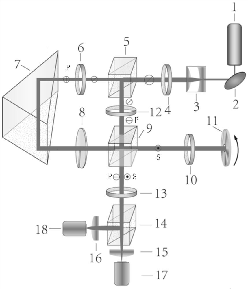
[0021] Such as figure 1 As shown, the schematic diagram of the optical system for angular velocity measurement of the present invention is provided, which consists of laser light source 1, total reflection mirror 2, beam expander mirror 3, first half-wave plate 4, first beam splitting prism 5, the first Two half wave plate 6, rectangular prism 7, spiral phase plate 8, polarizing beam splitter 9, quarter wave plate 10, first polarizer 12, second polarizer 13, second dichroic prism 14, first converging The lens 15, the second converging lens 16, the first photodetector 17 and the second photodetector 18 are composed, and the centers of all optical elements in the same direction are coaxial. The total reflection mirror 2, the beam expander 3 and the first half-wave plate 4 are sequentially arranged between the laser light source 1 and the first dichroic p...


PUM


Abstract

The invention discloses an optical system for angular velocity measurement. The optical system includes a laser light source, a first beam splitting prism, a polarization beam splitter, a second beamsplitting prism, a spiral phase sheet and a quarter wave plate; transmitted light and reflected light form signal light and reference light correspondingly after passing through the first beam splitting prism; and the spiral phase sheet converts the signal light into vortex light, the reference light completely transmitted by the polarization beam splitter and the vortex signal light completely reflected by the polarization beam splitter converge into one beam, the signal light and the reference light which converge into the one beam are same in polarization direction after passing through a second polarizing film, and optical heterodyne interference occurs. According to the optical system for angular velocity measurement, by rotating a first half wave plate, the light intensity ratio of the signal light after passing through a second half wave plate to the reference light after passing through the first polarizing film can be adjusted to enable the light intensity ratio of the vortexsignal light and the reference light which converge into the same one beam to be equal, the interference contrast is the largest at the time, and the differential electrical signal signal-to-noise ratio detected by a photoelectric detector is the highest.

Description

technical field [0001] The present invention relates to an optical system for angular velocity measurement, more specifically, to an optical system for realizing angular velocity measurement by utilizing the frequency shift phenomenon of vortex light irradiated on a rotating object. Background technique [0002] Vortices are one of the most common phenomena in nature, and they are ubiquitous in classical macroscopic systems such as water, clouds, and cyclones. A large number of theories and experiments have confirmed that vortices also exist in the optical wave field. Vortex light is a singular light with a spiral wavefront structure, and its beam center has a phase singularity, making its cross-sectional light intensity distributed in a ring-shaped hollow. As a form of wave, vortex light has orbital angular momentum due to the helical phase structure. In 1992, British physicist Professor Allen first confirmed that the orbital angular momentum of vortex light has quantum p...

Claims


Application Information

Patent Timeline
Patent Type & Authority Patents(China)
IPC IPC(8): G01P3/36
CPCG01P3/36
Inventor 董毅张艳玲田娅
Owner SHANDONG JIANZHU UNIV
Why Eureka
Try Eureka