Fatigue machine equipped with transmission rotating arm
A fatigue testing machine and actuating arm technology, which is applied in the direction of applying repetitive force/pulse force to test the strength of materials, can solve the problems of affecting the accuracy of fatigue experiments, small load range, and inconsistency with actual conditions, and achieve accurate tension and compression. The effect of load spectrum output, expanding the scope of fatigue experiments, and improving the scope of application
Active Publication Date: 2015-12-02
HOHAI UNIV
View PDF6 Cites 6 Cited by
- Summary
- Abstract
- Description
- Claims
- Application Information
AI Technical Summary
Problems solved by technology
[0006] 1. Fatigue testing machines mostly use the inertial force generated by the periodic rotation of the eccentric body to provide the test piece with an active load. The mass of the eccentric body is limited by the limit of the space and is small, so the load range generated by the testing machine is very small. The scope of the experiment is small
[0007] 2. The direction of the inertial force generated by the periodic rotation of the eccentric body is constantly changing, and it is directly loaded on the specimen, resulting in a constant change in the magnitude and direction of the force. The peak value of the load is the parameter set by the fatigue testing machine, which affects the fatigue. Accuracy of loading width
[0008] 3. The actual vehicle load is highly random, while the conventional fatigue testing machine can only provide periodic constant amplitude loading, which does not conform to the actual situation, thus affecting the accuracy of the fatigue test
[0009] 4. The conventional fatigue testing machine control system can only shut down the machine when the number of loading cycles is set, and cannot monitor fatigue cracks in real time. According to the crack generation status, the interactive shutdown machine is simple in form and single in function
Method used
View moreImage
Smart ImageViewing Examples

Examples
Embodiment 1
[0043] Embodiment 1: The present invention will be described in detail below through Embodiment 1.
Login to View More PUM
 Abstract
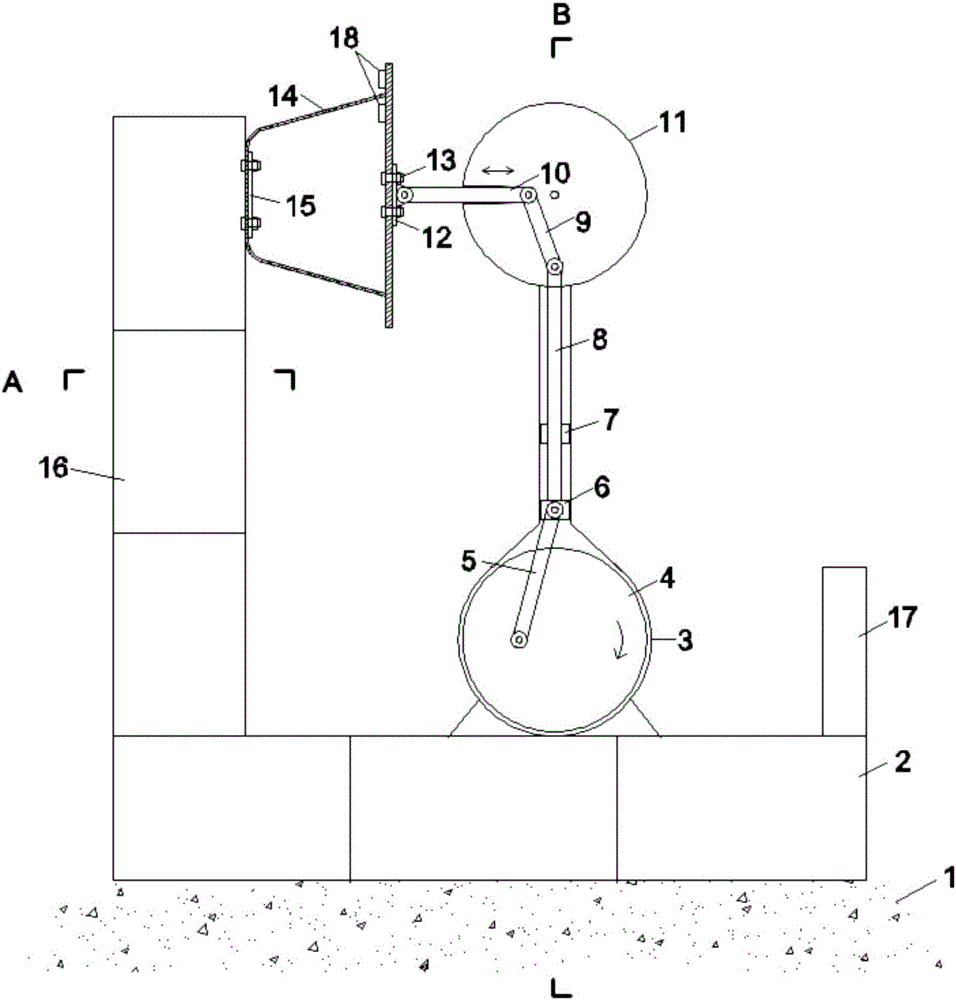
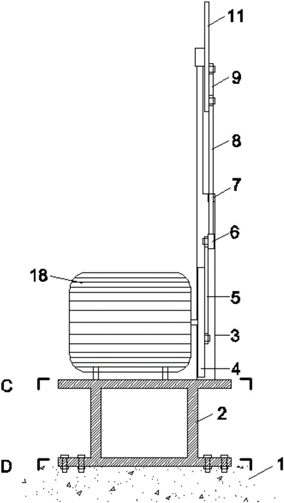
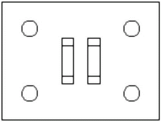
The invention discloses a fatigue machine equipped with a transmission rotating arm. The fatigue machine comprises a supporting frame, a metal guiding frame, an omni-directional transmission disc and acoustic emission probes, wherein the metal guiding frame is horizontally placed on the supporting frame; a rotating disc is mounted at the bottom of the metal guiding frame; the omni-directional transmission disc is arranged at the top of the metal guiding frame; a driving rod and a connecting rod are mounted on the metal guiding frame through a connecting block; the other end of the driving rod is connected to the rotating disc; the other end of the connecting rod extends upwards and is connected with a transmission rod and an actuating arm, namely the transmission rotating arm, in sequence; the actuating arm is connected with a test piece through a connecting plate; the test piece is fixed at the top end of the supporting frame; a control and display system is also mounted on the supporting frame; the connecting plate is equipped with the acoustic emission probes; the rotating disc is driven by a driving machine. The fatigue machine is relatively low in cost, complete in function, and relatively high in precision.
Description
technical field [0001] The invention belongs to the field of fatigue testing of bridge structures, in particular to a transmission arm type fatigue testing machine. Background technique [0002] With the development of the economy, the volume of vehicle traffic is increasing day by day, prompting my country to build more long-span bridges on large rivers, and the main girders of long-span bridges are mostly steel structures. Under the frequent action of vehicle loads, the steel Fatigue research issues are increasingly important. [0003] At present, most of the large-scale metal material fatigue tests are completed by the American MTS (full name is mechanical testing and simulation) hydraulic servo fatigue testing machine. The basic working principle of MTS is to provide the corresponding tensile and compressive loads to act on the specimen according to different requirements of the experiment. The MTS system has high precision and a wide range of applications. However, the ...
Claims
Login to View More Application Information
Patent Timeline
 IPC IPC(8): G01N3/32
Inventor 傅中秋吉伯海谢曙辉王益逊袁周致远
Owner HOHAI UNIV