
Grid equivalent simplification method considering system grid strength and generator effective transmission capacity

A technology of grid equivalent and sending capacity, applied in the direction of AC network circuits, electrical components, circuit devices, etc. Problems such as power consumption in situ

Active Publication Date: 2015-12-02
NARI TECH CO LTD +1
View PDF2 Cites 6 Cited by
  • Summary
  • Abstract
  • Description
  • Claims
  • Application Information

AI Technical Summary

Problems solved by technology

[0006] 1) The equivalent system is simplified to load, which cannot reflect the generator support capacity in the equivalent system;
[0007] 2) The equivalent system is simplified as a combination of generators and loads, but it cannot reflect the electromagnetic ring network connection and grid strength between different stations in the equivalent system;
[0008] 3) The constant power conversion technology is adopted in the equivalent system, that is, the sum of the loads in the equivalent system is used as the equivalent load level of the equivalent node, and the sum of the power generation in the equivalent system is used as the output of the equivalent generator. The processing method cannot reflect the power consumption characteristics in the vicinity of the generator in the equivalent system

Method used


Image

  • Grid equivalent simplification method considering system grid strength and generator effective transmission capacity
  • Grid equivalent simplification method considering system grid strength and generator effective transmission capacity
  • Grid equivalent simplification method considering system grid strength and generator effective transmission capacity

Examples


Embodiment Construction

[0058] The present invention will be described in further detail below with reference to the accompanying drawings.

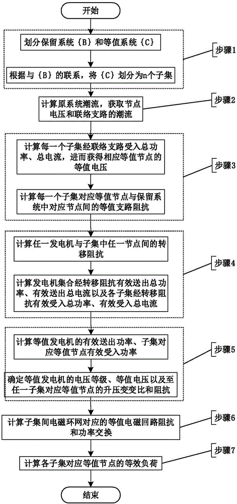
[0059] The flow process of the inventive method is as figure 1 As shown, including the following 7 steps:

[0060] 1) Divide the original system into the reserved system and the equivalent system, define the connection branch of the reserved system and the equivalent system on the side of the reserved system as {B}, and define the connection branch of the reserved system and the equivalent system at the equal The node set on the value system side is defined as {C}; for the nodes in the set {B}, the index is represented by the subscript i, i=1, 2, ..., n, n is the number of nodes in the set {B}; and For any node i in the set {B}, use the subset {C i} represents the set of nodes in the set {C} that have a connection relationship with node i, so that the nodes in the set {C} are divided into n subsets according to the connection relationship with each node in th...


PUM


Abstract

The present invention discloses a grid equivalent simplification method considering system grid strength and generator effective transmission capacity, belonging to the technical field of power system analysis. According to the method, the grid strength of a retention system and an equivalent system are characterized through the equivalent branch impedances of the retention system and the equivalent system, the grid strength in the equivalent system is characterized through the step-up transformer impedance from an equivalent generator in the equivalent system to equivalent buses, and the electromagnetic ring network link between different master stations is characterized through the equivalent electromagnetic loop impedance between the equivalent buses. At the same time, the generator effective transmission capacity in the equivalent system is characterized through effective transmission power of the generator via transfer impedance. The method can be used in the regional grid equivalence connected through a line and the low voltage grid equivalence which is connected to a main grid through a transformer branch. Compared with a disclosed grid equivalent simplification method, the topology relationship of an original grid can be more accurately reflected by the network after equivalence, and the physical meaning is clear.

Description

technical field [0001] The invention belongs to the technical field of power system analysis, and relates to a power system equivalent method, in particular to a power grid equivalent simplification method that takes into account the system grid strength and the effective sending capacity of a generator. Background technique [0002] With the rapid development of my country's UHV AC-DC power grid, large-scale DC-intensive access, the problem of AC-DC interaction is prominent. Existing power system electromechanical transient simulation programs can only simulate the system under the condition of fundamental wave symmetry. This limitation makes the simulation results different from the actual situation. In order to accurately simulate the transient characteristics of AC / DC power grids with multiple HVDC feed-in, it is usually necessary to use electromagnetic transient simulation analysis methods. Limited by the software scale of electromagnetic transients, it is often diffic...

Claims


Application Information

Patent Timeline
IPC IPC(8): H02J3/00
Inventor 侯玉强王玉李威彭慧敏李碧君李峰袁虎玲刘福锁黄志龙曹路李建华翟海保
Owner NARI TECH CO LTD
Learn More