Subsynchronous oscillation source location method and apparatus

A sub-synchronous oscillation and oscillation source technology, applied in the direction of circuit devices, AC network circuits, electrical components, etc., can solve the problems that the power line cannot be determined online, affecting the safe and stable operation of the power grid, and the safety of thermal power units

Active Publication Date: 2015-12-02
NR ELECTRIC CO LTD +1
View PDF3 Cites 19 Cited by
  • Summary
  • Abstract
  • Description
  • Claims
  • Application Information

AI Technical Summary

Problems solved by technology

In recent years, with the increasing maturity of wind power and photovoltaic power generation technologies, the cost of power generation has also gradually decreased, and large-scale commercial operation of wind power and photovoltaic power has become possible. By 2020, the installed capacity ratio of non-fossil energy and fossil energy in my country will be about 4:6. , the installed capacity of wind power and solar power generation reached about 300 million kilowatts, with an increase of about 180 million kilowatts; my country's large-scale wind and solar energy development areas are generally at the end of the power grid, while most of the grid load is located in the economically developed eastern and central regions. Electric energy can be efficiently and long-distance transported to the load centers in the central and eastern regions. UHV large-capacity transmission technology or EHV / UHV AC transmission with series compensation capacitors are often used. This type of power grid is used in wind turbine inverters, SVC, SVG, Sub-synchronous oscillations may occur under the action of various factors such as DC transmission and series compensation capacitors. The large-scale wind power bases that have been put into operation in my country have experienced multiple synchronous oscillations, which have seriously affected the safe and stable operation of the power grid and the The safety of thermal power units in the region
When subsynchronous oscillation occurs in the power grid, if the oscillation source can be located in real time online, it can lay a solid foundation for analyzing the causes of subsynchronous oscillation and taking further control measures. However, most of the current analysis methods for subsynchronous oscillation are based on PMU after the accident. Offline analysis of recording and broadcasting data, or only detecting whether subsynchronous oscillation occurs in a certain area, cannot determine which power line is the oscillation source online

Method used


Image

  • Subsynchronous oscillation source location method and apparatus
  • Subsynchronous oscillation source location method and apparatus
  • Subsynchronous oscillation source location method and apparatus

Examples


Embodiment 1

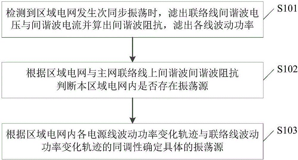
[0042] figure 1 Schematic diagram of the implementation process of this synchronous oscillation source location method Figure 1 ,Such as figure 1 As shown, the method for locating the synchronous oscillation source this time includes:

[0043]Step S101: Perform sub-synchronous oscillation detection according to the current and power signals of the connection line between the regional power grid and the main network, and obtain the detection result. The specific method is: set the current fluctuation threshold, power fluctuation threshold and a set of characteristic frequencies, satisfying the following Either condition, the detection result is a subsynchronous oscillation:

[0044] 1) When the fluctuation range of the effective value of the tie line current is greater than or equal to the current fluctuation threshold value, and the current fluctuation frequency satisfies any frequency characteristic in the above-mentioned group of characteristic frequencies;

[0045] 2) T...

Embodiment 2

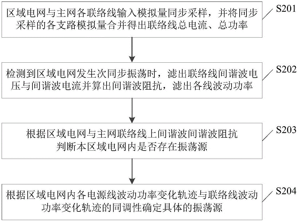
[0061] image 3 Schematic diagram of the implementation process of this synchronous oscillation source location method Figure II ,Such as image 3 As shown, the method for locating the synchronous oscillation source this time includes:

[0062] Step S201: Synchronous sampling of the input analog quantities of each tie line between the regional power grid and the main network, and combining the synchronously sampled analog quantities of each branch to obtain the total current and total power of the tie line;

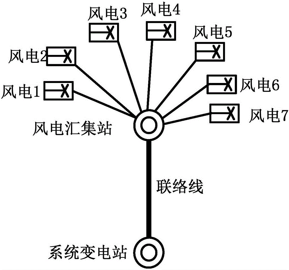
[0063] Specifically, such as Figure 4 The hub substation of the wind power base shown is connected to the system through a double-circuit line. First, the voltage and current signals of tie line 1 and tie line 2 are sampled synchronously, and combined to obtain the total current and total power flowing from the regional grid to the main grid, which will be used as a link for subsequent judgments. The total current and total power signal of the line, and the tie line ...

Embodiment 3

[0081] Figure 5 It is a schematic diagram of the composition and structure of the synchronous oscillation source positioning device, such as Figure 5 As shown, the device includes a subsynchronous oscillation detection module 301, a signal processing module 302, an oscillation source judgment module 303, and an oscillation source location module 304; wherein,

[0082] The sub-synchronous oscillation detection module 301 is used to detect whether sub-synchronous oscillation occurs in the regional power grid, and obtain the detection result;

[0083]The signal processing module 302 is used to perform signal processing on the connection line between the regional power grid and the main network and each power line in the regional power grid, filter out the interharmonic voltage and current components on the connection line between the regional power grid and the main network, and calculate Filter out the inter-harmonic impedance and filter out the fluctuating power in each line...


PUM


Abstract

The invention discloses a subsynchronous oscillation source location method and apparatus. The method comprises the following steps: when subsynchronouos oscillation of a regional power grid is detected, carrying out signal processing for a connection wire between the regional power grid and a main network as well as various power supply wires in the regional power grid, filtering components of interharmonics voltage and current on the connection wire between the regional power grid and the main network, calculating interharmonics impedance, filtering fluctuating power in each circuit power, judging whether an oscillation source exists in the regional power grid or not according to the interharmonics impedance of the connection wire between the regional power grid and the main network, and if the oscillation source exists, determining a specific oscillation source according to the coherence of a variation track of the fluctuating power of each power supply wire in the regional power grid and a variation track of the fluctuating power of the connection wire. The oscillation source in the regional power grid can be located by only acquiring the local information of a load-center substation without depending on the wide area information of different transformation substations and a communication network, and the construction of practical engineering is facilitated.

Description

technical field [0001] The invention relates to the field of power control, in particular to a method and device for locating a subsynchronous oscillation source. Background technique [0002] With the rapid economic growth and the rapid development of high energy-consuming industries, the demand for renewable new energy is becoming more and more urgent. In recent years, with the increasing maturity of wind power and photovoltaic power generation technologies, the cost of power generation has also gradually decreased, and large-scale commercial operation of wind power and photovoltaic power has become possible. By 2020, the installed capacity ratio of non-fossil energy and fossil energy in my country will be about 4:6. , the installed capacity of wind power and solar power generation reached about 300 million kilowatts, with an increase of about 180 million kilowatts; my country's large-scale wind and solar energy development areas are generally at the end of the power grid, ...

Claims


Application Information

Patent Timeline
Patent Type & Authority Applications(China)
IPC IPC(8): H02J3/00
Inventor 白杨任祖怡夏尚学常东旭王鹏翔
Owner NR ELECTRIC CO LTD
Why Eureka
Try Eureka