Cell combiner and DC power system therewith

A technology of DC power supply system and battery combiner, which is applied in the direction of battery circuit devices, current collectors, circuit devices, etc., and can solve the problems that battery packs cannot be directly used in parallel, batteries cannot be used, and batteries age rapidly, so as to achieve effective maintenance. And protection, prevent voltage shock battery pack, prolong the effect of service life

Active Publication Date: 2015-12-02
BEIJING DYNAMIC POWER CO LTD
View PDF6 Cites 9 Cited by
  • Summary
  • Abstract
  • Description
  • Claims
  • Application Information

AI Technical Summary

Problems solved by technology

[0005] Due to the characteristics of existing battery packs, only battery packs of the same capacity, same manufacturer, same type, and same batch can be connected to the same DC equipment, and battery packs of different capacities, different manufacturers, different types, and different batches cannot be connected directly Use them in parallel, otherwise, due to differences in battery parameters (such as battery internal resistance) between old and new batteries, batteries with different capacities, and batteries from different manufacturers, it will cause accelerated aging and damage to the battery.
If the user wants to increase the backup time of the DC power system or expand the load capacity, there will be greater requirements for the capacity of the battery pack. The current solution can only be realized by replacing all the battery packs at the same time, and it is impossible to add only one to the existing equipment. One or two new battery pack solutions to meet user needs
As a result, the existing batteries cannot be used, and new large-capacity batteries must be purchased, which leads to a waste of resources and an increase in costs.

Method used


Image

  • Cell combiner and DC power system therewith
  • Cell combiner and DC power system therewith
  • Cell combiner and DC power system therewith

Examples


Embodiment Construction

[0047] In order to make the object, technical solution and advantages of the present invention clearer, the implementation manner of the present invention will be further described in detail below in conjunction with the accompanying drawings.

[0048] The invention provides a battery combiner and a DC power supply system with the battery combiner.

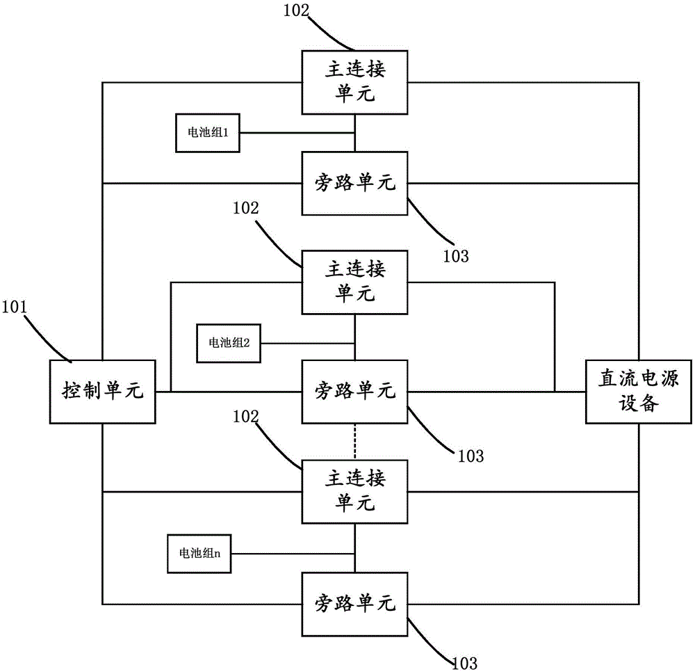
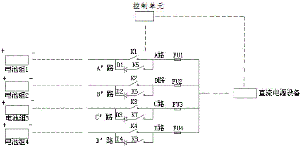
[0049] figure 1 It is a structural schematic diagram of a battery combiner provided by the present invention; the battery combiner includes: a control unit 101, at least two main connection units 102 and at least two bypass units 103;

[0050] The control unit is configured to communicate with the DC power supply equipment, and control the connection and disconnection of the main connection unit and the bypass unit according to the requirements of the DC power supply equipment;

[0051] The main connection unit is configured to turn on the parallel connection with the DC power supply device or disconnect the parallel connection w...


PUM


Abstract

The invention discloses a cell combiner and a DC power system therewith. The cell combiner comprises a control unit which is used for communication with DC power equipment, and controlling the on / off of a main connection unit and a bypass unit according to the demands of DC power equipment; the main connection unit which is used for the connection or disconnection of the parallel connection with the DC power equipment according to the indication of the control unit; and the bypass unit which is in parallel connection with two ends of the main connection unit, and is used for the disconnection of the main connection unit during the switching of a battery pack and starting the discharging of the DC power equipment, wherein the DC power equipment or the battery pack does not charge the battery pack. Through the above technical scheme of the invention, the cell combiner communicates with the DC power equipment, thereby achieving the independent management of each battery pack, achieving the effective maintenance and protection of the battery packs, prolonging the service life of the battery pack, and effectively preventing voltage from impacting on the battery pack in a switching process of the battery packs.

Description

technical field [0001] The invention relates to the technical field of power electronics, in particular to a battery combiner and a DC power supply system with the battery combiner. Background technique [0002] With the increasing development of science and technology, the battery, as an important guarantee function in the DC power system, is also an indispensable part of the DC power system. With the development of DC power supply, the requirement to integrate the existing storage batteries of DC power supply is becoming more and more urgent. If the existing DC power supply equipment needs to use battery packs directly in parallel, it can only be connected with batteries of the same capacity, same manufacturer, same type, and same batch. If the user wants to use the existing battery pack, that is, use batteries of different capacities, different manufacturers, different types, and different batches in parallel, the capacity expansion cannot be realized, and a new battery ...

Claims


Application Information

Patent Timeline
Patent Type & Authority Applications(China)
IPC IPC(8): H02J7/36H02J7/34
Inventor 张建向明芳
Owner BEIJING DYNAMIC POWER CO LTD
Why Eureka
Try Eureka