Method and apparatus for three-dimensional fabrication

A technology of equipment, three-dimensional objects, applied in the direction of manufacturing tools, additive manufacturing, opto-mechanical equipment, etc.

Active Publication Date: 2015-12-02
CARBON INC
View PDF48 Cites 39 Cited by
  • Summary
  • Abstract
  • Description
  • Claims
  • Application Information

AI Technical Summary

Problems solved by technology

These methods introduce mechanical steps that may complicate the equipment, slow down the process and / or may distort the final product
[0007] Continuous methods of producing three-dimensional objects are presented at some length in U.S. Patent No. 7,892,474 in terms of "top-down" techniques, but the reference does not explain how they may Implemented in a "bottom-up" system in a non-destructive manner to the produced artifacts

Method used


Image

  • Method and apparatus for three-dimensional fabrication
  • Method and apparatus for three-dimensional fabrication
  • Method and apparatus for three-dimensional fabrication

Examples


Embodiment approach

[0012] In some embodiments of continuous liquid phase interface printing, the first layer or region is provided immediately above, or in contact with, the build plate. The build plate is transparent to radiation that initiates polymerization (e.g., patterned radiation), but the build plate is preferably semipermeable to the polymerization inhibitor and allows the polymerization inhibitor (e.g., oxygen) to pass through it partially or completely (e.g., for continuous effectively feeds the inhibitor into the "dead zone"). The build plate is preferably "fixed" or "stationary", meaning that it does not need to slide, indent, spring back, etc. to produce discrete or sequential steps (as in a layer-by-layer process). Of course, minor movement of the build plate in the x and / or y directions (without unduly interrupting the polymerization gradient, but still allowing continuous polymerization of the liquid interface) may still accommodate some embodiments, also discussed below.

[00...

Embodiment 1

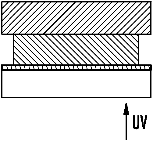
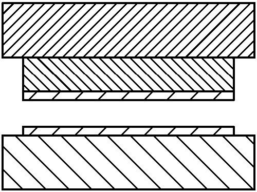
[0145] Inhibitor transfer from separate feed surface to build surface

[0146]A drop of ultraviolet (UV) curable adhesive was placed on the metal plate and covered with a 10 mm thick plate of TEFLON™ AF fluoropolymer (amorphous glassy polymer) as shown in Figure 5a. UV radiation was delivered to the adhesive from the TEFLONAF side, as shown in Figure 5b. After UV exposure, the two plates were separated. It was found that no force was required to separate the two plates. After testing the samples, it was found that only the adhesive near the metal plate was cured, and a thin film of uncured adhesive was present on the TeflonAF fluoropolymer plate and also on the cured portion of the adhesive, as shown in Figure 5c .

[0147] Two comparative experiments were also performed, using clean glass (Fig. 5d-5f) and glass treated with a release layer (Fig. 5g-5i). It was demonstrated that considerable force was required to separate the clean glass from the metal, and the adhesive ...

Embodiment 2

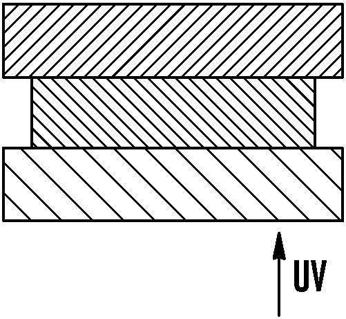
[0150] Inhibitors are transferred from the build plate to the build surface

[0151] Samples 1 and 2 were prepared in a similar manner, where a drop of UV-curable adhesive was placed on a metal plate and covered with a 10 mm thick TEFLON™ AF fluoropolymer plate, as shown in Figure 6a. Both samples were exposed to a nitrogen environment to eliminate any oxygen present, as shown in Fig. 6b. The next two samples were placed in standard atmospheric environment, and sample 1 was exposed to UV radiation immediately, while sample 2 was exposed to UV radiation for 10 minutes after atmospheric environment. Both samples were exposed to the same amount of UV radiation as Figure 6C and Figure 6E shown. In sample inspection after UV exposure, it was found that the adhesive was fully cured in Sample 1, as Figure 6D shown, and in sample 2 the adhesive cures only close to the metal plate, as Figure 6F shown. A film of uncured adhesive was present on the Teflon AF fluoropolymer pla...


PUM

PropertyMeasurementUnit
thicknessaaaaaaaaaa
thicknessaaaaaaaaaa
thicknessaaaaaaaaaa

Abstract

A method of forming a three-dimensional object, is carried out by (a) providing a carrier and a build plate, the build plate comprising a semipermeable member, the semipermeable member comprising a build surface with the build surface and the carrier defining a build region therebetween, and with the build surface in fluid communication by way of the semipermeable member with a source of polymerization inhibitor; (b) filling the build region with a polymerizable liquid, the polymerizable liquid contacting the build surface, (c) irradiating the build region through the build plate to produce a solid polymerized region in the build region, while forming or maintaining a liquid film release layer comprised of the polymerizable liquid formed between the solid polymerized region and the build surface, wherein the polymerization of which liquid film is inhibited by the polymerization inhibitor; and (d) advancing the carrier with the polymerized region adhered thereto away from the build surface on the build plate to create a subsequent build region between the polymerized region and the build surface while concurrently filling the subsequent build region with polymerizable liquid as in step (b). Apparatus for carrying out the method is also described.

Description

[0001] related application [0002] This application asserts the benefit of the following commonly owned patent applications: US Provisional Patent Application Serial No. 61 / 919,903, filed December 23, 2013 (Case No. 1151-3PR2); 61 / 865,841, filed August 14, 2013 (Case No. 1151-3PR) and 61 / 763,746 (Case No. 1151-2PR), filed February 12, 2013, the disclosures of which are incorporated herein by reference in their entirety. field of invention [0003] The present invention relates to methods and apparatus for producing solid three-dimensional objects from liquid polymerizable materials. Background of the invention [0004] In conventional additive or 3D manufacturing techniques, the construction of a 3D object takes place step-by-step or layer-by-layer. In particular, layer formation takes place by curing of photocurable resins under the action of visible or UV light irradiation. Two techniques are known: one in which the new layer is formed on the upper surface of the growi...

Claims


Application Information

Patent Timeline
Patent Type & Authority Applications(China)
IPC IPC(8): G03F7/00
CPCG03F7/0037B29C67/0066B29C64/135G03F7/027G03F7/038G03F7/38B29C33/0061B29C64/124B29C64/129B29C64/393B29C64/40B29C2033/0005B29K2071/02B29K2105/0005B29K2105/0058B29K2827/12B29K2883/005B29K2995/0026B29K2995/0065B33Y10/00B33Y30/00B33Y50/02B33Y80/00A61F2/82A61F2240/001A61M37/0015B29C35/0888B29C2035/0827B29K2067/00B29K2995/006B29L2031/753B29L2031/7534G05B2219/00G05B2219/49016
Inventor J.M.德西蒙A.埃尔莫什金E.T.萨穆尔斯基
Owner CARBON INC
Why Eureka
Try Eureka