Wiring device for rotating scanning of cone beam CT machine

A wiring device and cone beam technology, which is applied in the field of rotary scanning wiring devices of cone beam CT machines, can solve the problems of increasing the width of the scanning disk, unsatisfactory actual effect, and bloated whole machine, so as to reduce the axial width, shorten the range of motion, The effect of smooth cable pulling

Active Publication Date: 2015-12-09
SUZHOU INST OF BIOMEDICAL ENG & TECH CHINESE ACADEMY OF SCI
View PDF9 Cites 15 Cited by
  • Summary
  • Abstract
  • Description
  • Claims
  • Application Information

AI Technical Summary

Problems solved by technology

[0004] Different from helical CT axially moving and continuously rotating scanning, cone beam CT is generally driven by a synchronous belt, and only needs to rotate and scan 360-degree effective data to reconstruct and obtain multiple tomographic images. If the power supply and communication methods use carbon brushes and The low-voltage slip ring technology is too costly and has a waste of functions. If a rotary drag chain is installed on the end face of the synchronous pulley on the back side of the scanning disk, the width of the scanning disk will be greatly increased, and the whole machine will appear bloated.
Although other overly complex wiring methods can meet the requirements of power supply and communication, there are safety hazards such as scattered, pulled, and twisted cables, and the actual effect is not ideal

Method used


Image

  • Wiring device for rotating scanning of cone beam CT machine
  • Wiring device for rotating scanning of cone beam CT machine
  • Wiring device for rotating scanning of cone beam CT machine

Examples


Embodiment Construction

[0044] The present invention will be further described in detail below in conjunction with the accompanying drawings, so that those skilled in the art can implement it with reference to the description.

[0045] It should be understood that terms such as "having", "comprising" and "including" as used herein do not entail the presence or addition of one or more other elements or combinations thereof.

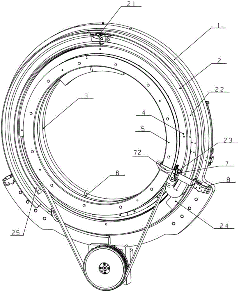
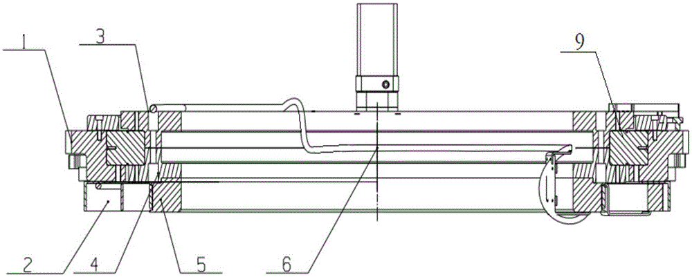
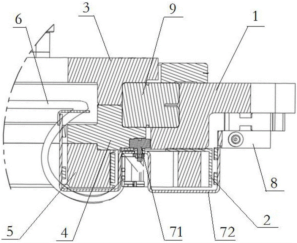
[0046] Such as Figure 1-12 As shown, the present invention provides a rotary scanning wiring device for a cone beam CT machine, including:

[0047] Frame 1, the lower ends of its two sides are erected vertically on the base of the CT machine through brackets 14, and fixed with the base, the base can move freely, such as Figure 6 , as shown in 11 and 12, the inside of the frame 1 is provided with a slewing bearing 9;

[0048] The rotating part has a turntable 3, a flange 4 and a synchronous pulley 5. The turntable 3 and the flange 4 are connected by clamping the inner ring of ...


PUM


Abstract

The invention discloses a wiring device for rotating scanning of a cone beam CT machine. The wiring device comprises a rack, a rotating part, a drag chain and a follower, wherein the rack is vertically arranged on the base of the CT machine; a pivotal bearing is arranged in the rack; the rotating part comprises a rotating disk, a flange and a synchronous pulley; the rotating disk and the flange are connected in a manner that the inner ring of the pivotal bearing is clamped by bolts; the synchronous pulley and the outer side wall of the flange are connected by bolts, and is connected with a belt pulley; the fixed end of the drag chain is arranged at the right upper end of the rack; the movable end of the drag chain is movably arranged on the side wall of the rack; the follower comprises a servo roller and a servo bent board connected with the servo roller; the servo roller is movably arranged in the space between the flange and the rack; the servo bent board is arranged on the surface of the rotating part in a bridge manner, and is tightly and fixedly connected with the movable end of the drag chain. The wiring device is compact in structure, safe and reliable in working, and cables are smoothly pulled.

Description

technical field [0001] The invention relates to the technical field of CT scanners, and more specifically, the invention relates to a rotary scanning wiring device for a cone-beam CT machine. Background technique [0002] Mobile CT scanners are a major innovation in the history of CT in recent years. The world's first mobile bedside CT scanner - CereTom, launched by NeuroLogica Corporation of the United States in 2005, provides services for diagnosis and treatment of patients in wards, emergency rooms, ICU and other places, realizing a people-centered service method, representing A development direction of CT scanner in the future. Because of its outstanding innovation, CereTom won the 2006 Frost & Sullivan Medical Imaging Product Invention Award and the 2006 Medical Design Gold Award. [0003] Since the birth of the CT scanner in the last century, it has mainly experienced several stages of single-detector parallel beam scanning, multi-detector fan-beam scanning, single-r...

Claims


Application Information

Patent Timeline
Patent Type & Authority Applications(China)
IPC IPC(8): A61B6/03
Inventor 曾维俊孙海旋孙明山徐品邢晓曼王钟周王鹏
Owner SUZHOU INST OF BIOMEDICAL ENG & TECH CHINESE ACADEMY OF SCI
Why Eureka
Try Eureka