Adjustable test tube holder

A test tube clamp, adjustable technology, applied in the direction of test tube holder/clamp, etc., can solve the problem of small diameter range and achieve the effect of large adjustable range

Inactive Publication Date: 2015-12-09
CHONGQING CHANGFENG CHEM IND
View PDF1 Cites 3 Cited by
  • Summary
  • Abstract
  • Description
  • Claims
  • Application Information

AI Technical Summary

Problems solved by technology

[0004] Although the above invention patent can clamp test tubes with different diameters, the diameter range that can be clamped is too small

Method used


Image

  • Adjustable test tube holder
  • Adjustable test tube holder
  • Adjustable test tube holder

Examples


Embodiment 1

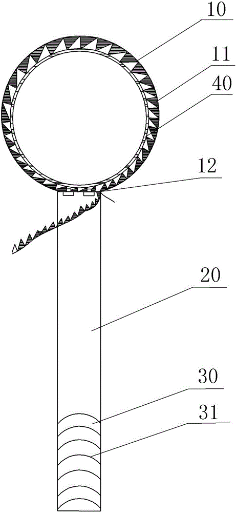
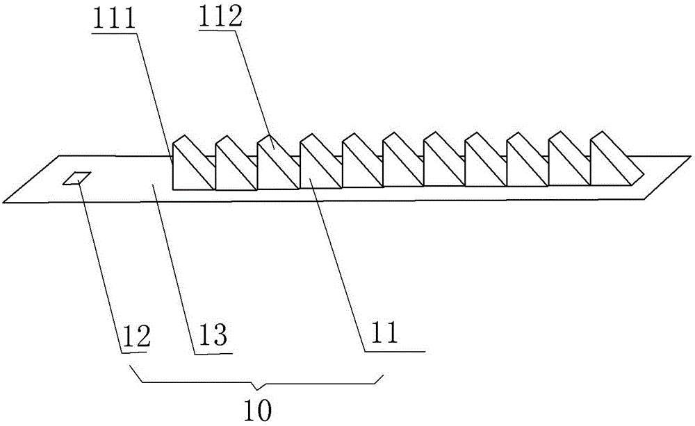
[0021] Embodiment one is basically as attached figure 1 And attached figure 2 Shown:

[0022] Adjustable test tube clamp, including handle 20, polyphenylene ether plastic heat-resistant ring 10 (hereinafter referred to as: heat-resistant ring 10), rubber anti-slip sleeve 30: heat-resistant ring 10 is integrally formed, including heat-resistant ring body 13, positioning hole 12 and Teeth 11, positioning holes 12 and teeth 11 are arranged on the heat-resistant ring body 13; wherein the positioning hole 12 is rectangular, its long side is parallel to the axial direction of the heat-resistant ring 10, and the positioning hole 12 is located at one end of the heat-resistant ring body 13 At least 1cm; tooth 11 includes a blocking surface 111 and a forward surface 112, wherein the blocking surface 111 is perpendicular to the heat-resistant ring body 13, and the advancing surface 112 has an included angle with the heat-resistant ring body 13; when unfolded, the advancing surface 112 ...

Embodiment 2

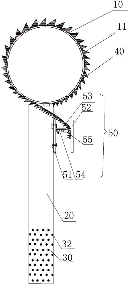
[0024] Embodiment two is basically as attached image 3 As shown: the difference between this implementation and the first embodiment is that the polyimide plastic heat-resistant ring 10 (hereinafter referred to as: heat-resistant ring 10 ) is used, and the rubber anti-slip sleeve 30 used has granular protrusions 32 on the outside. Also comprise buckle 50 in addition; Buckle 50 comprises fixed plate 51, baffle plate 53, limit plate 52, connecting rod, block 55, compression spring 54; Fixed plate 51 is fixed on the handle 20 by bolt connection; Welded on the fixed plate 51 and the limit plate 52 respectively; the baffle plate 53 is welded vertically on the fixed plate 51, the distance between the baffle plate 53 and the limit plate 52 is the height of the tooth 11, the baffle plate 53 is next to the compression spring 54, Set on the top of the compression spring 54; the compression spring 54 and the stopper 55 are arranged between the fixed plate 51 and the limit plate 52; one ...

Embodiment 3

[0026] Embodiment 3: The difference between this embodiment and Embodiment 1 is that the polyphenylene sulfide plastic heat-resistant ring is used, and the fixed connection method between the polyphenylene sulfide plastic heat-resistant ring and the handle is riveting. This embodiment can achieve the same clamping effect as the first embodiment.


PUM


Abstract

The invention discloses chemical laboratory equipment and particularly relates to an adjustable test tube holder. The adjustable test tube holder comprises a handle and a heat-resisting ring, wherein the heat-resisting ring is integrally formed and comprises a heat-resisting ring body, a positioning hole and teeth, and the positioning hole and the teeth are all arranged on the heat-resisting ring body; the positioning hole is rectangular, the long edge of the positioning hole is parallel to the axis direction of the heat-resisting ring, and the positioning hole is formed in the position with a distance of at least 1 cm away from one end of the heat-resisting ring body; each tooth comprises an advancing surface and a blocking surface, the blocking surface is perpendicular to the wall of the heat-resisting ring body, and an included angle is formed between the advancing surface and the heat-resisting ring body; when the test tube holder is unfolded, each advancing surface is far away from the positioning hole, and each blocking surface is close to the positioning hole; the size of each tooth is matched with the positioning hole, and a plurality of teeth are arranged on one side of the heat-resisting ring body sequentially; the heat-resisting ring body is fixedly connected with the handle. The test tube holder can clamp test tubes with different diameters, has a larger adjustable range and has broad application prospects in chemical experiments.

Description

technical field [0001] The invention relates to a chemical laboratory equipment, in particular to an adjustable test tube clamp. Background technique [0002] In chemical experiments, it is often necessary to heat the test tube. Since the glass test tube wall will become hot when heated, it cannot be directly grasped by hand, so test tube clamps are often used. Common test tube clamps are mostly made of wood, and it consists of a short handle, a long handle and a fixed spring, and the holding parts of the long handle and the short handle embrace a circle. This test tube clamp can only clamp test tubes of one diameter, and the scope of application is too narrow. [0003] The patent document of Chinese Patent Publication No. CN102350386A discloses a test tube clamp that can clamp test tubes of different diameters. The test tube clamp has a non-slip handle that is easy to hold; one end of the handle is fixedly connected to a long cylindrical screw; the front of the screw is f...

Claims


Application Information

Patent Timeline
IPC IPC(8): B01L9/06
Inventor 李定山
Owner CHONGQING CHANGFENG CHEM IND
Why Eureka
Try Eureka