
A clamping punching fixture for inertia friction welding

A punching jig and friction welding technology, applied in the field of clamping punching jig for inertia friction welding, can solve the problems of inability to carry out continuous production, waste of cost and efficiency, and difficulty in clamping parts, so as to avoid difficulty in clamping and save money. cost, the effect of prolonging the service life

Active Publication Date: 2017-11-14
北京航为高科连接技术有限公司
View PDF9 Cites 0 Cited by
  • Summary
  • Abstract
  • Description
  • Claims
  • Application Information

AI Technical Summary

Problems solved by technology

During the punching process of the part, the edge of the fixture and the flash is easily worn, and viscous materials such as titanium alloy are also easily adhered to the inner hole of the punching die, resulting in part of the flash being inserted into the fixture with the part In the hole, it is very difficult to clamp the part again, and continuous production cannot be carried out
At this time, the entire fixture needs to be replaced, resulting in a great waste of cost and efficiency

Method used


Image

  • A clamping punching fixture for inertia friction welding
  • A clamping punching fixture for inertia friction welding
  • A clamping punching fixture for inertia friction welding

Examples


Embodiment Construction

[0024] In order to have a clearer understanding of the technical features, purposes and effects of the present invention, the specific implementation manners of the present invention will now be described with reference to the accompanying drawings.

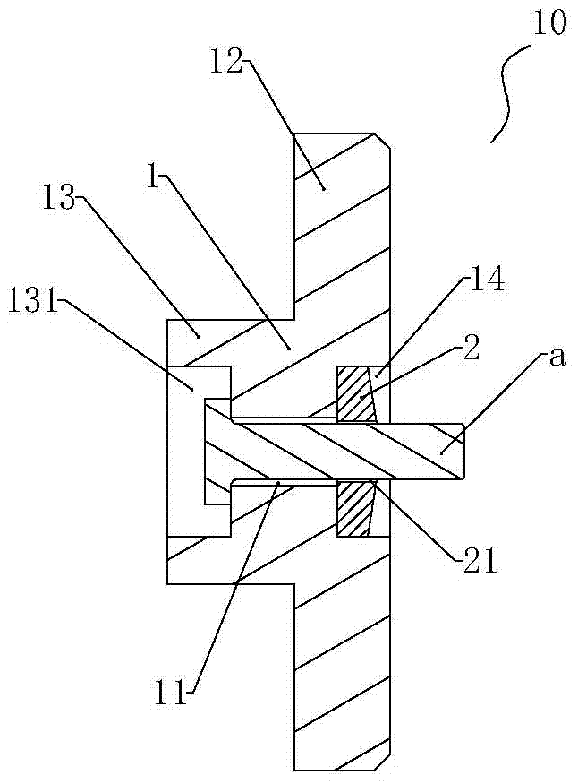
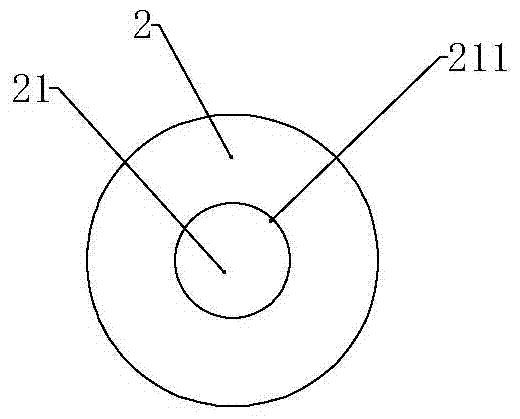
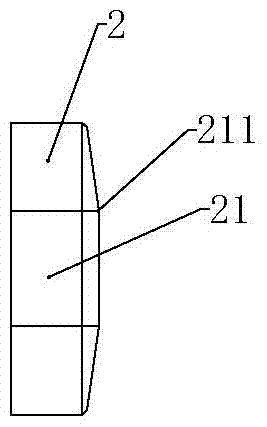
[0025] Such as figure 1 As shown, the present invention provides a clamping and punching fixture 10 for inertia friction welding, which is used for welding small rod-shaped parts, such as bimetallic rivets, and can continue to cut off welding burrs after welding is completed. Different from the prior art, the clamping and punching jig 10 includes a detachable and split jig base 1 and a punching core 2 . The fixture base 1 is provided with a first channel 11 for passing through the workpiece. The rod-shaped workpiece a has heads of various shapes such as countersunk heads, flat heads, etc., and the diameter of the head is larger than that of the rod. The workpiece a passes through the first passage 11, and the diameter of the he...


PUM


Abstract

The invention provides a clamping punching clamp for inertia friction welding. The clamping punching clamp comprises a clamp base and a punching core, wherein a communicated first passage for penetrating a workpiepe is arranged on the clamp base; the punching core is fixed to the clamp base in a demountable manner, and positioned on the outer side at one end of the first passage; a second passage which has the same axis with the first passage and allows the workpiepe to penetrate is arranged on the punching core; the inner diameter of the first passage is larger than that of the second passage. The punching core of the clamping punching clamp is easy to replace after being worn, while replacing the whole clamp is not required, so that the service life of the clamp is prolonged, and the cost is reduced. The clamp adopts a split-type different inner diameter structure, and the size of an inner hole where punched scraps are likely to accumulate is increased, so that the problem that part clamping is difficult is avoided. The punching core adopts a semi-spiral or raised structure, so that welding burrs can be cut into pieces effectively, and are prevented from sticking to the inner hole of the punching core, and the service life of the punching hole is prolonged accordingly.

Description

technical field [0001] The invention relates to a welding jig used on an inertial friction welding machine, in particular to a clamping and punching jig for inertial friction welding. Background technique [0002] Inertial friction welding is a method that generates heat by friction between the materials to be welded, and the materials undergo plastic deformation under the action of upsetting force to realize the connection. After inertia friction welding is completed, weld flash is produced between the two parts being joined. There are two ways to remove welding flash of parts. Large parts generally use turning to remove flash, while small parts (such as bimetallic rivets) are usually punched and welded directly on the clamping tool due to their small size and need to be mass-produced. After the parts are welded, the welding flash must be removed before the parts can be removed. The current method of removing the flash is basically to make the welding flash contact with ...

Claims


Application Information

Patent Timeline
Patent Type & Authority Patents(China)
IPC IPC(8): B23K20/12B23K20/26
CPCB23K20/12B23K20/26
Inventor 刘健光刘风雷梁福顺梁晔赵庆云
Owner 北京航为高科连接技术有限公司
Learn More