Double-gun welding device and machining method

A welding device and welding method technology, applied in the direction of auxiliary devices, welding equipment, auxiliary welding equipment, etc., can solve the problems of multiple welding procedures and low welding efficiency of multi-section pipe fittings, achieve reduced processing procedures, high welding quality, and reduced labor costs Effect

Inactive Publication Date: 2015-12-09
CHONGQING JINLUN MACHINERY MFG CO LTD
View PDF0 Cites 9 Cited by
  • Summary
  • Abstract
  • Description
  • Claims
  • Application Information

AI Technical Summary

Problems solved by technology

[0003] One object of the present invention is to provide a double-gun welding device to solve the pr

Method used


Image

  • Double-gun welding device and machining method

Examples


Embodiment 1

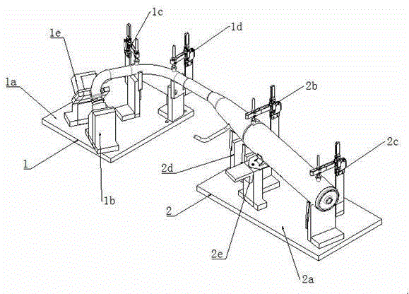
[0020] Example 1, such as figure 1 As shown, a double-gun welding device is provided in this embodiment, including a welding machine and a clamp; the welding machine has two welding torches; the clamp includes a first clamp 1 and a second clamp 2, and the first clamp 1 includes a first clamp body 1a, a first clamp jaw 1b, a second clamp jaw 1c, and a third clamp jaw 1d; the first clamp jaw 1b, the second clamp jaw 1c and the third clamp jaw 1d are all fixed on the On the first clamping body 1a; a pneumatic clamping device 1e is also fixed on the first clamping body 1a. The end of the pipe is clamped by the pneumatic clamping device 1e, so as to avoid shaking and loosening of the end of the pipe during the rotation of the clamp and affect the welding quality. The second clamp 2 includes a second clamp body 2a, a fourth clamp jaw 2b, and a fifth clamp jaw 2c, and the fourth clamp jaw 2b and the fifth clamp jaw 2c are fixed on the second clamp body 2a; It includes a clamp rotat...

Embodiment 2

[0022] Embodiment 2, a double-gun welding method is provided in this embodiment, comprising the following steps:

[0023] (1) Sleeve the two ends of the second pipe on the first pipe and the third pipe respectively;

[0024] (2) Clamp and fix the first pipe with the first jaw, the second jaw and the third jaw, clamp and fix the third pipe with the fourth jaw and the fifth jaw, and the fixed first pipe and the second The three pipes support and position the second pipe;

[0025] (3) Adjust the two welding torches of the welding machine to both ends of the second pipe respectively, aiming at the weld between the second pipe and the first pipe and the seam between the second pipe and the third pipe respectively;

[0026](4) Start the welding machine for welding, and simultaneously start the fixture rotation device to rotate the first fixture and the second fixture synchronously to complete the circumferential welding of the pipe fittings.

[0027] The distance between the weldi...


PUM

PropertyMeasurementUnit
Lengthaaaaaaaaaa
Diameteraaaaaaaaaa

Abstract

The invention discloses a double-gun welding device and a machining method, and belongs to the field of automobile mufflers. The method includes the steps that chamfering is conducted on pipes needing to be welded first; then the pipes are fixed to special clamps; afterwards, welded joints between the pipes are welded through two welding guns at the same time; the clamps are rotated while welding is conducted, so that circumferential welding of the pipes is achieved. The device comprises a welding machine and the clamps. The clamps comprise the first clamp and the second clamp. The first clamp comprises a clamp body and a plurality of clamping jaws fixed to the clamp body. The second clamp comprises a clamp body and a plurality of clamping jaws fixed to the clamp body. The device further comprises clamp rotating devices. The welding guns of the welding machine are located between the first clamp and the second clamp. By the adoption of the method and structure, circumferential welding can be conducted on multiple points between multiple sections of an automobile muffler pipeline at the same time, manual spot welding fixation is needless, labor cost is reduced, the machining procedure is simplified, manual operation is reduced, machining precision is improved, product quality is improved and production efficiency is improved obviously.

Description

technical field [0001] The invention relates to the field of automobile muffler manufacturing, in particular to a double gun welding device and a processing method. Background technique [0002] With the development of my country's economy, people's demand for automobiles has also increased. At present, the development of my country's auto parts industry is still in a very weak stage. There is still an obvious gap between the development speed of domestic parts and international brands. gap. As one of the parts of automobiles, mufflers always encounter many insurmountable problems in daily production. The vehicle muffler is usually composed of three pipe fittings with different diameters connected together. The three pipe fittings include the first pipe, the second pipe and the third pipe. In order to ensure that the muffler can work normally, the connection accuracy between the pipe fittings is required to be high. . The connection method of the vehicle muffler is basical...

Claims


Application Information

Patent Timeline
IPC IPC(8): B23K37/053
CPCB23K37/0538
Inventor 吴明喜
Owner CHONGQING JINLUN MACHINERY MFG CO LTD
Why Eureka
Try Eureka